List of gear nomenclature
This page lists the standard US nomenclature used in the description of mechanical gear construction and function, together with definitions of the terms.
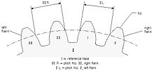
The surface of the gear blank at the outer ends of the teeth is customarily formed to such a back cone.
Reasons for requiring backlash include allowing for lubrication and thermal expansion, and to prevent jamming.
CP = Circular Pitch in inches DP = Diametral Pitch CP = π / DP [3] The composite action test (double flank) is a method of inspection in which the work gear is rolled in tight double flank contact with a master gear or a specified gear, in order to determine (radial) composite variations (deviations).
[1] and this is composite action test for double flank Cone distance in a bevel gear is the general term for the distance along an element of the pitch cone from the apex to any given position in the teeth.
The face width of a gear is the length of teeth in an axial plane.
[1] Total face width is the actual dimension of a gear blank including the portion that exceeds the effective face width, or as in double helical gears where the total face width includes any distance or gap separating right hand and left hand helices.
For a cylindrical gear, effective face width is the portion that contacts the mating teeth.
For a bevel gear, different definitions for effective face width are applicable.
[1] A helical rack has a planar pitch surface and teeth that are oblique to the direction of motion.
A condition wherein the actual tooth flank position was nearer to the datum tooth flank, in the specified measuring path direction (clockwise or counterclockwise), than the theoretical position would be considered a minus (-) deviation.
The direction of tolerancing for index deviation along the arc of the tolerance diameter circle within the transverse plane.
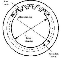
The inside cylinder is the surface that coincides with the tops of the teeth of an internal cylindrical gear.
[1] Expressed as θ, the involute polar angle is the angle between a radius vector to a point, P, on an involute curve and a radial line to the intersection, A, of the curve with the base circle.
[1] Lead is the axial advance of a helix gear tooth during one complete turn (360°), that is, the Lead is the axial travel (length along the axle) for one single complete helical revolution about the pitch diameter of the gear.
It is similar to the Diametral Pitch (DP), which is commonly used for UK system (inch measure) gears but they differ in the units used and in that they bear a reciprocal relationship.
Module may also be applied to UK system gears, using inch units, but this usage is not in common use.
MM = Metric Module PD = Pitch Circle Diameter in mm n = Number of Teeth MM = PD / n UK system (inch measure) gears are more commonly specified with the Diametral Pitch (DP) which is the number of teeth per inch of diameter of the pitch circle.
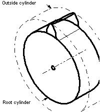
The outside (tip or addendum) cylinder is the surface that coincides with the tops of the teeth of an external cylindrical gear.
In external and internal bevel gears, the pitch angles are respectively less than and greater than 90 degrees.
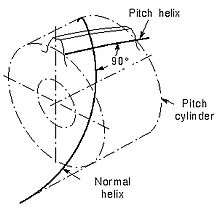
The outside (tip or addendum) helix is the intersection of the tooth surface and the outside cylinder of a helical gear or cylindrical worm.
[1] Pitch surfaces are the imaginary planes, cylinders, or cones that roll together without slipping.
In gears with parallel axes, the transverse and the plane of rotation coincide.
[1] Tooth-to-tooth radial composite deviation (double flank) is the greatest change in center distance while the gear being tested is rotated through any angle of 360 degree/z during double flank composite action test.
Total radial composite deviation (double flank) is the total change in center distance while the gear being tested is rotated one complete revolution during a double flank composite action test.
[1] The root cone is the imaginary surface that coincides with the bottoms of the tooth spaces in a bevel or hypoid gear.
[1] The root cylinder is the imaginary surface that coincides with the bottoms of the tooth spaces in a cylindrical gear.
A spur gear has a cylindrical pitch surface and teeth that are parallel to the axis.
[1] A spur rack has a planar pitch surface and straight teeth that are at right angles to the direction of motion.
Test radius is not the same as the operating pitch radii of two tightly meshing gears unless both are perfect and to basic or standard tooth thickness.