AC motor
The AC motor commonly consists of two basic parts, an outside stator having coils supplied with alternating current to produce a rotating magnetic field, and an inside rotor attached to the output shaft producing a second rotating magnetic field.
The brushless wound-rotor doubly fed synchronous motor system has an independently excited rotor winding that does not rely on the principles of slip-induction of current.
[3] The first person to conceive of a rotating magnetic field was Walter Baily, who gave a workable demonstration of his battery-operated polyphase motor aided by a commutator on 28 June 1879, to the Physical Society of London.
[4] Describing an apparatus nearly identical to Baily's, French electrical engineer Marcel Deprez published a paper in 1880 that identified the rotating magnetic field principle and that of a two-phase AC system of currents to produce it.
[5] Never practically demonstrated, the design was flawed, as one of the two currents was “furnished by the machine itself.”[4] In 1886, English engineer Elihu Thomson built an AC motor by expanding upon the induction-repulsion principle and his wattmeter.
[6] In 1887, American inventor Charles Schenk Bradley was the first to patent a two-phase AC power transmission with four wires.
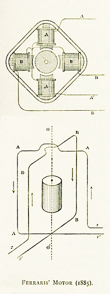
[citation needed] "Commutatorless" alternating current induction motors seem to have been independently invented by Galileo Ferraris and Nikola Tesla.
Actual RPM for an induction motor will be less than this calculated synchronous speed by an amount known as slip, that increases with the torque produced.
This kind of rotor is the basic hardware for induction regulators, which is an exception of the use of rotating magnetic field as pure electrical (not electromechanical) application.
It is typically cast aluminum or copper poured between the iron laminates of the rotor, and usually only the end rings will be visible.
Furthermore, a stalled squirrel-cage motor (overloaded or with a jammed shaft) will consume current limited only by circuit resistance as it attempts to start.
In this case, the rotor has the same number of poles as the stator and the windings are made of wire, connected to slip rings on the shaft.
In certain high-power variable-speed wound rotor drives, the slip-frequency energy is captured, rectified, and returned to the power supply through an inverter.
Transistorized drives can directly vary the applied voltage as required by the starting characteristics of the motor and load.
Two-phase servo motors are inherently high-speed, low-torque devices, heavily geared down to drive the load.
This causes a time lag in the flux passing through the shading coil, so that the maximum field intensity moves higher across the pole face on each cycle.
This produces a low level rotating magnetic field which is large enough to turn both the rotor and its attached load.
When the speed of the motor is sufficient to overcome the inertia of the load, the contacts are opened automatically by a centrifugal switch or electric relay.
The start winding is made mainly of thin wire with fewer turns to make it high resistive and less inductive.
The main winding is made with thicker wire with larger number of turns which makes it less resistive and more inductive.
Because inertia makes it difficult to instantly accelerate the rotor from stopped to synchronous speed, these motors normally require some sort of special feature to get started.
On startup, when slip decreases sufficiently, the rotor becomes magnetized by the stator's field, and the poles stay in place.
Universal motors can run on AC as well as DC provided the frequency is not so high that the inductive reactance of the stator winding and eddy current losses become problems.
Universal motors are compact, have high starting torque and can be varied in speed over a wide range with relatively simple controls such as rheostats and PWM choppers.
By transformer action, the stator induces currents in the rotor, which create torque by repulsion instead of attraction as in other motors.
These are two-phase induction motors with permanent magnets to retard the rotor so its speed is accurately proportional to the power passing through the meter.
The mechanical dial on the meter reads disc rotations and the total net energy delivered to the load.
(If the load supplies power to the grid, the disc rotates backwards unless prevented by a ratchet, thus making net metering possible.)
Representative are low-torque synchronous motors with a multi-pole hollow cylindrical magnet (internal poles) surrounding the stator structure.
At each end of the coil are a pair of circular plates with rectangular teeth on their edges, formed so they are parallel with the shaft.