Coil winding technology
Coils are used as components of circuits, and to provide the magnetic field of motors, transformers, and generators, and in the manufacture of loudspeakers and microphones.
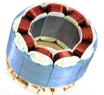
The rotor and stator are both assembled from a stack of laminations stamped from sheets of electrical steel, typically 1 mm thick.
Effects of bends and tolerances of the wire and the coil body as well as changing surface qualities can be avoided that way.
In certain circumstances it can be completely performed without a relocating movement, if the distance from the nozzle to the coil is that long that the force component against the guiding behavior of the wire itself has no longer an effect.
This wire parking pin can either be a clamp or a copy of a post that is wrapped at the coil similar to the termination process.
0.3 mm can be torn normally by a tearing pen that passes close to the post of the coil or the wire guiding nozzle itself.
The separating point should be very close to the post of the coil in order not to impede a subsequent contacting process (soldering, welding etc.).
An advantage is that the needle support carrying the wire guiding nozzle is normally coupled to a CNC coordinate system.
With the needle winding technology, it is possible to produce a finished assembly such as stator coils or a connection and contacting onto a machine.
Because of the higher performance density, brushless EC drives (electronically commutated motors) with permanent magnet rotors are increasingly used instead of the asynchronous technology.
For producing asynchronous motors, drawing-in systems are usually used that are initially winding air-core coils only to draw them later into the stator with a tool.
In contrast, the concentrated winding of EC stators is more flexible in the manufacturing process, energy saving when implemented, better adjustable during operation and it requires less space.
The coil groups are frequently manufactured with flyer winding machines and put onto the insertion tool with a transfer instrument.
In small-batch manufacturing, the coil groups are relocated manually from the winding masks to the insertion tool using transfer instruments.
When using large conductor cross-sections, this may possibly lead to high losses and an undesired heat development in the stator winding.
This is either executed by using an enameled wire receiving a bonding electric current during moulding or by cold forming which is followed by impregnation.
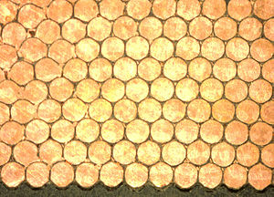
The particular benefit of this process technology lies in the fact that the winding machine produces a completely wound assembly group when adequate electrical slot fill factors are employed.
Since manufacturing a functioning stator merely requires a small effort, the negative impact on the electric fill factor is gladly accepted.
In order to be able to use various additional functions of the winding machine, the end plates are often designed in a way which allows e.g. the taking on of cutting terminal contacts.
The plastic end plates are designed in a way that the sides of the injected shafts insulate half of the stator slot.
However, a disadvantage constitutes in the fact that the depth of the shot of the injection process is limited depending on the stator lengths and the plastic material used.
In addition, the diversity in types is only conditionally lucrative since a new injection mould needs to be produced whenever the length of the package or the laminations changes.
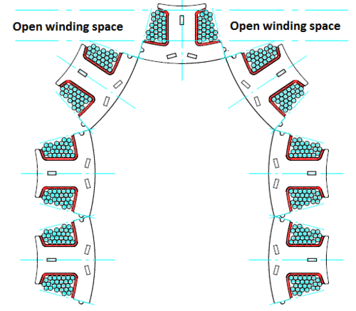
The latter may be bodiless or wound onto a coil body and subsequently be transferred to a T-segment or directly to the stator laminations, depending on the application.
The main reason for the processing of T-segments into one tooth chain lies in the reduced of number of contact points.
When using high current with low operating power, this type of manufacture is especially beneficial since it reduces contact resistances and potential errors.
Usually, it is taken care of with adhesive tape or pole or bag-type forming of the tooth's frontal insulation where the wire may be attached after the winding process.
Single teeth are easy to handle, whereas tooth chains must be built in carefully, taking into account the risk of damaging the connecting wires.
Toothed chains of a phase connected in series are rarely produced since, compared with the already difficult assembly of phase-wise wound T-segments, they will be followed by further assembly movements (pushing onto the stator pack) and the changing length ratios of the connecting wires between the coil sections of a phase.
A minimum number of contact points – with the advantages of the linear wound single tooth creates a maximum fill factor.
As the phases U, V and W as well as multiple stators can be wound at the same time, the needle winding technique has a high performance density in connection with the use of toothed chains.