Commutator (electric)
It consists of a cylinder composed of multiple metal contact segments on the rotating armature of the machine.
The first direct current commutator-type machine, the dynamo, was built by Hippolyte Pixii in 1832, based on a suggestion by André-Marie Ampère.
A commutator consists of a set of contact bars fixed to the rotating shaft of a machine, and connected to the armature windings.
In a motor, the armature current causes the fixed magnetic field to exert a rotational force, or a torque, on the winding to make it turn.
Two or more fixed brushes connect to the external circuit, either a source of current for a motor or a load for a generator.
Insulating wedges around the perimeter of each segment are pressed so that the commutator maintains its mechanical stability throughout its normal operating range.
In small appliance and tool motors the segments are typically crimped permanently in place and cannot be removed.
In addition to the commonly used heat, torque, and tonnage methods of seasoning commutators, some high performance commutator applications require a more expensive, specific "spin seasoning" process or over-speed spin-testing to guarantee stability of the individual segments and prevent premature wear of the carbon brushes.
Such requirements are common with traction, military, aerospace, nuclear, mining, and high speed applications where clamping failure and segment or insulation protrusion can lead to serious negative consequences.
Carbon brushes, being made of a softer material, wear faster and may be designed to be replaced easily without dismantling the machine.
The commutator on small motors (say, less than a kilowatt rating) is not designed to be repaired through the life of the device.
Early machines used brushes made from strands of copper wire to contact the surface of the commutator.
Modern rotating machines with commutators almost exclusively use carbon brushes, which may have copper powder mixed in to improve conductivity.
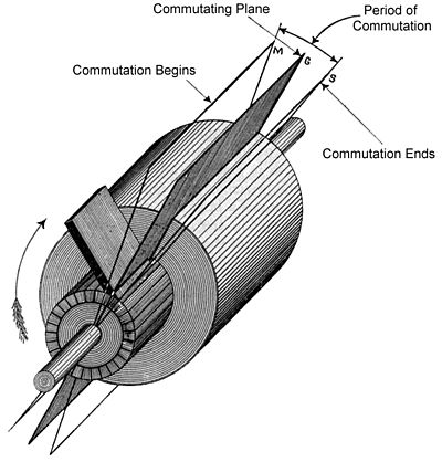
Motors and generators suffer from a phenomenon known as 'armature reaction', one of the effects of which is to change the position at which the current reversal through the windings should ideally take place as the loading varies.
To conduct sufficient current to or from the commutator, the brush contact area is not a thin line but instead a rectangular patch across the segments.
Most introductions to motor and generator design start with a simple two-pole device with the brushes arranged at a perfect 90-degree angle from the field.
This ideal is useful as a starting point for understanding how the fields interact but it is not how a motor or generator functions in actual practice.
Instead, the rotation of the rotor induces field effects which drag and distort the magnetic lines of the outer non-rotating stator.
It is therefore difficult to build an efficient reversible commutated dynamo, since for highest field strength it is necessary to move the brushes to the opposite side of the normal neutral plane.
These effects can be mitigated by a compensation winding in the face of the field pole that carries armature current.
In the coils of the rotor, even after the brush has been reached, currents tend to continue to flow for a brief moment, resulting in a wasted energy as heat due to the brush spanning across several commutator segments and the current short-circuiting across the segments.
By applying a dynamic varying field to the interpoles as the load, RPM, or direction of rotation of the device changes, it is possible to balance out field distortions from armature reaction so that the brush position can remain fixed and sparking across the segments is minimized.
A sensor keeps track of the rotor position and semiconductor switches such as transistors reverse the current.
Brushes opposite each other are connected to each other (not to an external circuit), and transformer action induces currents into the rotor that develop torque by repulsion.
[17] This consists of a block of wood or ebonite with four wells, containing mercury, which are cross connected by copper wires.