Dimmer
By changing the voltage waveform applied to the lamp, it is possible to lower the intensity of the light output.
Although variable-voltage devices are used for various purposes, the term dimmer is generally reserved for those intended to control light output from resistive incandescent, halogen, and (more recently) compact fluorescent lamps (CFLs) and light-emitting diodes (LEDs).
More specialized equipment is needed to dim fluorescent, mercury-vapor, solid-state, and other arc lighting.
Dimmers with direct manual control had a limit on the speed they could be varied at but this problem has been largely eliminated with modern digital units (although very fast changes in brightness may still be avoided for other reasons like lamp life).
Most recently, software programmable internal dimmers can use signals from the same switch that turns lights on and off to control dimming.
Their cost is about the same as the older "dimmability" circuitry that they replace in LED bulbs, fixtures or drivers.
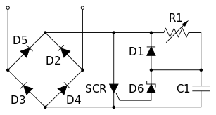
[1] In 1959, Joel S. Spira, who would found the Lutron Electronics Company in 1961, invented a dimmer based on a then-new solid state switching device called a Silicon Controlled Rectifier or SCR.
This small device allowed the dimmer to be installed in a standard electrical wall box while saving energy.
More recent digital control protocols such as DMX512, DALI, or one of the many Ethernet-based protocols like Art-Net, ETCnet, sACN, Pathport, ShowNet or KiNET[5] enable the control of a large number of dimmers (and other stage equipment) through a single cable.
Dimmers based on rheostats were inefficient since they would dissipate a significant portion of the power rating of the load as heat.
Their voltage output, and so their dimming effect, is largely independent of the load applied so it was far easier to design the lighting that would be attached to each autotransformer channel.
For instance, the control room of an audio recording studio may require an extremely strict limit for electromagnetic interference.
Semiconductor dimmers switch on at an adjustable time (phase angle) after the start of each alternating-current half-cycle, thereby altering the voltage waveform applied to lamps and so changing its RMS effective value.
This development also made it possible to make dimmers small enough to be used in place (within the pattress) of normal domestic light switches.
When the dimmer is at 50% power, the switches are switching their highest voltage (>325 V in Europe) and the sudden surge of power causes the coils on the inductor to move, creating a buzzing sound associated with some types of dimmer; this same effect can be heard in the filaments of the incandescent lamps as "singing".
The suppression circuitry might be insufficient to prevent buzzing to be heard on sensitive audio and radio equipment that shares the mains supply with the lighting loads.
[8] European dimmers must comply with relevant EMC legislation requirements; this involves suppressing the emissions described above to limits described in EN55104.
Dimmers based on insulated-gate bipolar transistors (IGBTs) do away with most of the noise present in TRIACs by chopping off the falling side of the sine wave.
An even newer, but still expensive technology is sine-wave dimming, which is implemented as a high-power switched-mode power supply followed by a filter.
In architectural installations electricity is run straight from the dimmers to the lights via permanent wiring (this is called a circuit).
Switching high-intensity incandescent (filament) lamps to full power from cold can shorten their life dramatically, owing to the large inrush current that occurs.
In less advanced systems, this same effect is achieved by literally pre-heating (warming) the globes before an event or performance.
Modern digital desks can emulate preheat and dimmer curves and allow a soft patch to be done in memory.
Unsurprisingly, a longer rise time is more expensive to implement than a short one, this is because the size of choke has to be increased.