Diode bridge
[1] When used in its most common application, for conversion of an alternating-current (AC) input into a direct-current (DC) output, it is known as a bridge rectifier.
The diode bridge circuit was invented by Karol Pollak and patented in December 1895 in Great Britain[3] and in January 1896 in Germany.
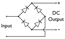
A diode bridge uses diodes as series components to allow current to pass in the forward direction during the positive part of the AC cycle and as shunt components to redirect current flowing in the reverse direction during the negative part of the AC cycle to the opposite rails.
In the diagrams below, when the input connected to the left corner of the diamond is positive, and the input connected to the right corner is negative, current flows from the upper supply terminal to the right along the red (positive) path to the output and returns to the lower supply terminal through the blue (negative) path.
When the input connected to the left corner is negative, and the input connected to the right corner is positive, current flows from the lower supply terminal to the right along the red (positive) path to the output and returns to the upper supply terminal through the blue (negative) path.
The final stage of rectification may consist of a zener diode-based voltage regulator, which almost completely eliminates any residual ripple.