H-bridge
These circuits are often used in robotics and other applications to allow DC motors to run forwards or backwards.
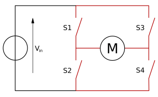
[1] The name is derived from its common schematic diagram representation, with four switching elements configured as the branches of a letter "H" and the load connected as the cross-bar.
Using the nomenclature above, the switches S1 and S2 should never be closed at the same time, as this would cause a short circuit on the input voltage source.
The "short"(see below in "DC motor driver" section) cases are dangerous to the power source and to the switches.
Apart from changing the rotation direction, the H-bridge can provide additional operation modes, "brake" and "free run until frictional stop".
A solid-state H-bridge is typically constructed using opposite polarity devices, such as PNP bipolar junction transistors (BJT) or P-channel MOSFETs connected to the high voltage bus and NPN BJTs or N-channel MOSFETs connected to the low voltage bus.
This requires a more complex design since the gates of the high side MOSFETs must be driven positive with respect to the DC supply rail.
Many integrated circuit MOSFET gate drivers include a charge pump within the device to achieve this.
The outputs of the transformer are usually clamped by Zener diodes, because high voltage spikes could destroy the MOSFET gates.
A common variation of this circuit uses just the two transistors on one side of the load, similar to a class AB amplifier.
This eliminates the shoot-through failure mode, and is commonly used to drive variable or switched reluctance machines and actuators where bi-directional current flow is not required.
The L293x series, being technically mostly obsolete since the late 1970s due to decreased switching losses and higher speeds in more modern semiconductor products, is still found in many hobbyist circuitry.