Dislocation
In 1934, Egon Orowan, Michael Polanyi and G. I. Taylor, proposed that the low stresses observed to produce plastic deformation compared to theoretical predictions at the time could be explained in terms of the theory of dislocations.
In 1934, Egon Orowan, Michael Polanyi and G. I. Taylor, independently proposed that plastic deformation could be explained in terms of the theory of dislocations.
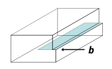
In effect, a half plane of atoms is moved in response to shear stress by breaking and reforming a line of bonds, one (or a few) at a time.
Even this simple model of the force required to move a dislocation shows that plasticity is possible at much lower stresses than in a perfect crystal.
A dislocation is a linear crystallographic defect or irregularity within a crystal structure which contains an abrupt change in the arrangement of atoms.
Dislocations define the boundary between slipped and unslipped regions of material and cannot end within a lattice and must either extend to a free edge or form a loop within the crystal.
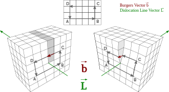
[1] A dislocation can be characterised by a vector comprising the distance and direction of relative movement it causes to atoms as it moves through the lattice.
The movement of mobile dislocations allow atoms to slide over each other at low stress levels and is known as glide or slip.
The number and arrangement of dislocations give rise to many of the properties of metals such as ductility, hardness and yield strength.
Heat treatment, alloy content and cold working can change the number and arrangement of the dislocation population and how they move and interact in order to create useful properties.
Three mechanisms for dislocation formation are homogeneous nucleation, grain boundary initiation, and interfaces between the lattice and the surface, precipitates, dispersed phases, or reinforcing fibers.
The creation of a dislocation by homogeneous nucleation is a result of the rupture of the atomic bonds along a line in the lattice.
The steps and ledges at the grain boundary are an important source of dislocations in the early stages of plastic deformation.
[11] PSB's are so-called, because they leave marks on the surface of metals that even when removed by polishing, return at the same place with continued cycling.
[11] Where PSB's meet the surface, extrusions and intrusions form, which under repeated cyclic loading, can lead to the initiation of a fatigue crack.
Dislocation velocity is largely dependent upon shear stress and temperature, and can often be fit using a power law function:[14] where
Greater phonon scattering at higher temperatures is hypothesized to be responsible for increased damping forces which slow the dislocation movement.
[15] A screw dislocation can be visualized by cutting a crystal along a plane and slipping one half across the other by a lattice vector, the halves fitting back together without leaving a defect.
It comprises a structure in which a helical path is traced around the linear defect (dislocation line) by the atomic planes in the crystal lattice.
In a twist boundary, the misalignment between adjacent crystal grains occurs due to the cumulative effect of screw dislocations within the material.
These dislocations cause a rotational misorientation between the adjacent grains, leading to a twist-like deformation along the boundary.
Twist boundaries can significantly influence the mechanical and electrical properties of materials, affecting phenomena such as grain boundary sliding, creep, and fracture behavior[17] The stresses caused by a screw dislocation are less complex than those of an edge dislocation and need only one equation, as symmetry allows one radial coordinate to be used:[15] where
[15] If the Burgers vector is very large, the core may actually be empty resulting in a micropipe, as commonly observed in silicon carbide.
Materials with low stacking-fault energies have the greatest dislocation dissociation and are therefore more readily cold worked.
[20] Away from the melting point of a material, vacancy diffusion is a slow process, so jogs act as immobile barriers at room temperature for most metals.
The lateral spreading of a kink from the nucleation point allows for forward propagation of the dislocation while only moving a few atoms at a time, reducing the overall energy barrier to slip.
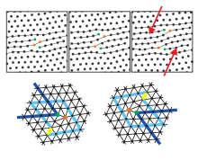
Those dislocations are topological point defects which implies that they cannot be created isolated by an affine transformation without cutting the hexagonal crystal up to infinity (or at least up to its border).
The orientational order is not yet destroyed (as indicated by lattice lines in one direction) and one finds - very similar to liquid crystals - a fluid phase with typically a six-folded director field.
The isotropic fluid phase appears, if the dislocations dissociate into isolated five-folded and seven-folded disclinations.
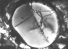
If the material is deformed and repeatedly re-etched, a series of etch pits can be produced which effectively trace the movement of the dislocation in question.