Effective radiated power
It is the total power in watts that would have to be radiated by a half-wave dipole antenna to give the same radiation intensity (signal strength or power flux density in watts per square meter) as the actual source antenna at a distant receiver located in the direction of the antenna's strongest beam (main lobe).
An alternate parameter that measures the same thing is effective isotropic radiated power (EIRP).
Since a half-wave dipole antenna has a gain of 1.64 (or 2.15 dB) compared to an isotropic radiator, if ERP and EIRP are expressed in watts their relation is
6 dBi) will have the same signal strength in the direction of its main lobe, and thus the same ERP and EIRP, as a 4,000 watt transmitter feeding an antenna with a gain of 1× (equiv.
So ERP and EIRP are measures of radiated power that can compare different combinations of transmitters and antennas on an equal basis.
ERP and EIRP are always greater than the actual total power radiated by the antenna.
The transmitter is usually connected to the antenna through a transmission line and impedance matching network.
Maximum directivity of an ideal half-wave dipole is a constant, i.e., 0 dBd = 2.15 dBi .
The ideal dipole antenna could be further replaced by an isotropic radiator (a purely mathematical device which cannot exist in the real world), and the receiver cannot know the difference so long as the input power is increased by 2.15 dB.
The distinction between dBd and dBi is often left unstated and the reader is sometimes forced to infer which was used.
Since it is constructed from dipoles, often its antenna gain is expressed in dBd, but listed only as dB.
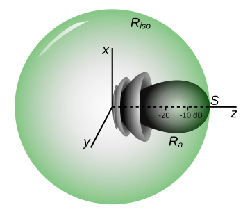
Let us assume a 100 watt (20 dBW) transmitter with losses of 6 dB prior to the antenna.
Therefore, anywhere along the side-lobe direction from this transmitter, a blind receiver could not tell the difference if a Yagi–Uda was replaced with either an ideal dipole (oriented towards the receiver) or an isotropic radiator with antenna input power increased by 1.57 dB.
For example, a cellular telephone tower has a fixed linear polarization, but the mobile handset must function well at any arbitrary orientation.
Therefore, a handset design might provide dual polarization receive on the handset so that captured energy is maximized regardless of orientation, or the designer might use a circularly polarized antenna and account for the extra 3 dB of loss with amplification.
The transmitter power output (TPO) of such a station typically may be 10,000–20,000 watts, with a gain factor of 5–10× (5–10×, or 7–10 dB).
Rather than the average power over all directions, it is the apparent power in the direction of the peak of the antenna's main lobe that is quoted as a station's ERP (this statement is just another way of stating the definition of ERP).
This is particularly applicable to the huge ERPs reported for shortwave broadcasting stations, which use very narrow beam widths to get their signals across continents and oceans.
ERP for FM radio in the United States is always relative to a theoretical reference half-wave dipole antenna.
(That is, when calculating ERP, the most direct approach is to work with antenna gain in dBd).
To deal with antenna polarization, the Federal Communications Commission (FCC) lists ERP in both the horizontal and vertical measurements for FM and TV.
The maximum ERP for US FM broadcasting is usually 100,000 watts (FM Zone II) or 50,000 watts (in the generally more densely populated Zones I and I-A), though exact restrictions vary depending on the class of license and the antenna height above average terrain (HAAT).
For most microwave systems, a completely non-directional isotropic antenna (one which radiates equally and perfectly well in every direction – a physical impossibility) is used as a reference antenna, and then one speaks of EIRP (effective isotropic radiated power) rather than ERP.
This includes satellite transponders, radar, and other systems which use microwave dishes and reflectors rather than dipole-style antennas.
Omnidirectional antennas used by a number of stations radiate the signal equally in all horizontal directions.
While antenna efficiency and ground conductivity are taken into account when designing such an array, the FCC database shows the station's transmitter power output, not ERP.
[8] Effective monopole radiated power (EMRP) may be used in Europe, particularly in relation to medium wave broadcasting antennas.
[7] Cymomotive force (CMF) is an alternative term used for expressing radiation intensity in volts, particularly at the lower frequencies.
[7] It is used in Australian legislation regulating AM broadcasting services, which describes it as: "for a transmitter, [it] means the product, expressed in volts, of: It relates to AM broadcasting only, and expresses the field strength in "microvolts per metre at a distance of 1 kilometre from the transmitting antenna".
[8] The height above average terrain for VHF and higher frequencies is extremely important when considering ERP, as the signal coverage (broadcast range) produced by a given ERP dramatically increases with antenna height.