Electrolytic capacitor
A solid, liquid, or gel electrolyte covers the surface of this oxide layer, serving as the cathode or negative plate of the capacitor.
They are widely used for decoupling or noise filtering in power supplies and DC link circuits for variable-frequency drives, for coupling signals between amplifier stages, and storing energy as in a flashlamp.
Electrolytic capacitors are polarized components because of their asymmetrical construction and must be operated with a higher potential (i.e., more positive) on the anode than on the cathode at all times.
They not only provide the cheapest solutions for high capacitance or voltage values for decoupling and buffering purposes but are also insensitive to low ohmic charging and discharging as well as to low-energy transients.
In such a comparison the values for ESR and ripple current load are the most important parameters for the use of electrolytic capacitors in modern electronic equipment.
The phenomenon that in an electrochemical process, aluminium and such metals as tantalum, niobium, manganese, titanium, zinc, cadmium, etc., can form an oxide layer which blocks an electric current from flowing in one direction but which allows current to flow in the opposite direction, was first observed in 1857 by the German physicist and chemist Johann Heinrich Buff (1805–1878).
The first more common application of wet aluminium electrolytic capacitors was in large telephone exchanges, to reduce relay hash (noise) on the 48 volt DC power supply.
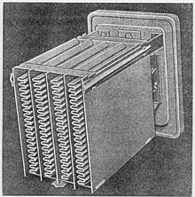
The development of AC-operated domestic radio receivers in the late 1920s created a demand for large-capacitance (for the time) and high-voltage capacitors for the valve amplifier technique, typically at least 4 microfarads and rated at around 500 volts DC.
Waxed paper and oiled silk film capacitors were available, but devices with that order of capacitance and voltage rating were bulky and prohibitively expensive.
The ancestor of the modern electrolytic capacitor was patented by Samuel Ruben in 1925,[12][13] who teamed with Philip Mallory, the founder of the battery company that is now known as Duracell International.
[14] At the same time in Berlin, Germany, the "Hydra-Werke", an AEG company, started the production of electrolytic capacitors in large quantities.
For aluminium electrolytic capacitors the decades from 1970 to 1990 were marked by the development of various new professional series specifically suited to certain industrial applications, for example with very low leakage currents or with long life characteristics, or for higher temperatures up to 125 °C.
The relevant development of solid electrolyte tantalum capacitors began some years after William Shockley, John Bardeen and Walter Houser Brattain invented the transistor in 1947.
They ground tantalum to a powder, which they pressed into a cylindrical form and then sintered at a high temperature between 1500 and 2000 °C under vacuum conditions, to produce a pellet ("slug").
These capacitors used a solid organic conductor, the charge transfer salt TTF-TCNQ (tetracyanoquinodimethane), which provided an improvement in conductivity by a factor of 10 compared with the manganese dioxide electrolyte.
[5] For tantalum electrolytic capacitors lowering the voltage applied increases the reliability and reduces the expected failure rate.
On the alternate halves of the AC cycles, one of the oxides on the foil acts as a blocking dielectric, preventing reverse current from damaging the electrolyte of the other one.
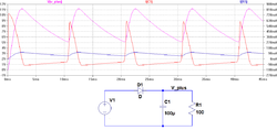
This dissipation power loss PL is caused by ESR and is the squared value of the effective (RMS) ripple current IR.
This property is a result of the limited ion movability in the liquid electrolyte, which slows down the voltage ramp across the dielectric, and of the capacitor's ESR.
[51][52] Solid Tantalum capacitors which are exposed to surge, peak or pulse currents, for example, in highly inductive circuits, should be used with a voltage derating.
[72] Applying a positive voltage to a "wet" capacitor causes a reforming (self-healing) process which repairs all weakened dielectric layers, and the leakage current remain at a low level.
For other conditions of applied voltage, current load, temperature, capacitance value, circuit resistance (for tantalum capacitors), mechanical influences and humidity, the FIT figure can be converted with acceleration factors standardized for industrial[81] or military[82] applications.
Continuous improvement in tantalum powder and capacitor technologies have resulted in a significant reduction in the amount of impurities which formerly caused most field crystallization failures.
The constant random failure rate period corresponds to the lifetime or service life of “wet” aluminium electrolytic capacitors.
With today's high levels of purity in the manufacture of electrolytic capacitors it is not to be expected that short circuits occur after the end-of-life-point with progressive evaporation combined with parameter degradation.
They use different ways for specification, some give special formulas,[90][91] others specify their e-caps lifetime calculation with graphs that consider the influence of applied voltage.
Application rules for types with an intrinsic failure mode are specified to ensure capacitors with high reliability and long life.
All electrolytic capacitors are "aged" during manufacturing by applying the rated voltage at high temperature for a sufficient time to repair all cracks and weaknesses that may have occurred during production.
Most modern electrolytic systems are chemically inert and do not exhibit corrosion problems, even after storage times of two years or longer.
This is performed by applying the rated voltage to the capacitor via a series resistor of approximately 1 kΩ for one hour, allowing the oxide layer to repair itself through self-healing.