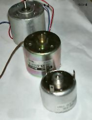
Brushed DC electric motor
Brushed DC motors can be varied in speed by changing the operating voltage or the strength of the magnetic field.
Brushed motors continue to be used for electrical propulsion, cranes, paper machines and steel rolling mills.
According to Fleming's left hand rule, the forces cause a turning effect on the coil, making it rotate.
With this modification, it can also be effectively turned off simply by stalling (stopping) it in a position in the zero-torque (i.e. commutator non-contacting) angle range.
A clear downside of this simple solution is that the motor now coasts through a substantial arc of rotation twice per revolution and the torque is pulsed.
This may work for electric fans or to keep a flywheel spinning but there are many applications, even where starting and stopping are not necessary, for which it is completely inadequate, such as driving the capstan of a tape transport, or any similar instance where to speed up and slow down often and quickly is a requirement.
Even for fans and flywheels, the clear weaknesses remaining in this design—especially that it is not self-starting from all positions—make it impractical for working use, especially considering the better alternatives that exist.
The back EMF is the reason that the motor when free-running does not appear to have the same low electrical resistance as the wire contained in its winding.
Instead, as the rotor spins it induces field effects which drag and distort the magnetic lines of the outer non-rotating stator.
It is therefore difficult to build an efficient reversible commutated dynamo, since for highest field strength it is necessary to move the brushes to the opposite side of the normal neutral plane.
The field coils have conventionally existed in four basic formats: separately excited (sepex), series-wound, shunt-wound, and a combination of the latter two, compound-wound.
Permanent magnets have conventionally only been useful in small motors because it was difficult to find a material capable of retaining a high-strength field.
The effective voltage can be varied by inserting a series resistor or by an electronically controlled switching device made of thyristors, transistors, or, formerly, mercury arc rectifiers.
An electric locomotive or train would typically have four motors which could be grouped in three different ways: This provided three running speeds with minimal resistance losses.
When the field is weakened, the back-emf reduces, so a larger current flows through the armature winding and this increases the speed.
Since the series-wound DC motor develops its highest torque at low speed, it is often used in traction applications such as electric locomotives, and trams.
When motor current increases, the control will disconnect the resistor and low speed torque is made available.
It found service in almost any environment where good speed control was required, from passenger lifts through to large mine pit head winding gear and even industrial process machinery and electric cranes.
In many applications, the motor-generator set was often left permanently running, to avoid the delays that would otherwise be caused by starting it up as required.
Although electronic (thyristor) controllers have replaced most small to medium Ward-Leonard systems, some very large ones (thousands of horsepower) remain in service.
The generator output current is in excess of 15,000 amperes, which would be prohibitively expensive (and inefficient) to control directly with thyristors.
The series wound DC motor's most notable characteristic is that its speed is almost entirely dependent on the torque required to drive the load.
Bi-metal thermal overload protectors are embedded in the motor's windings and made from two dissimilar metals.
They are designed such that the bimetallic strips will bend in opposite directions when a temperature set point is reached to open the control circuit and de-energize the motor.
In addition, motors can be protected from overvoltages or surges with isolation transformers, power conditioning equipment, MOVs, arresters and harmonic filters.
Environmental conditions, such as dust, explosive vapors, water, and high ambient temperatures, can adversely affect the operation of a DC motor.
This current can make an excessive voltage drop affecting other equipment in the circuit and even trip overload protective devices.
Therefore, the need arises for an additional resistance in series with the armature to limit the current until the motor rotation can build up the counter-emf.
The starting rheostat was less expensive, but had smaller resistance elements that would burn out if required to run a motor at a constant reduced speed.
It also has overcurrent protection that trips the lever to the off position if excessive current over a set amount is detected.


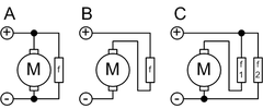
- A, Shunt
- B, Series
- C, Compound
- f, Field coil
