Waveguide filter
Waveguide filters were developed during World War II to meet the needs of radar and electronic countermeasures, but afterwards soon found civilian applications such as use in microwave links.
Much of post-war development was concerned with reducing the bulk and weight of these filters, first by using new analysis techniques that led to elimination of unnecessary components, then by innovations such as dual-mode cavities and novel materials such as ceramic resonators.
Transmission line[o] technologies such as conducting wires and microstrip can be thought of as waveguides,[3] but are not commonly called such and are also outside the scope of this article.
Amongst the uses of waveguide filters are the construction of duplexers, diplexers,[d] and multiplexers; selectivity and noise limitation in receivers; and harmonic distortion suppression in transmitters.
The conductors constrain the currents to be parallel to the line, and consequently both the magnetic and electric components of the electromagnetic field are perpendicular to the direction of travel of the wave.
However, they are important in the functioning of certain filter components such as irises and posts, described later, because energy is stored in the evanescent wave fields.
On the other hand, filters whose operating frequencies are so high that the wavelengths are sub-millimetre cannot be manufactured with normal machine shop processes.
In some applications which require rigorous filtering, the walls are plated with a thin layer of gold or silver to improve surface conductivity.
He described this in terms of the wave reflecting repeatedly off the internal wall of the outer conductor in a zig-zag fashion as it progressed down the waveguide.
[27] Mason and Sykes' work was focused on the formats of coaxial cable and balanced pairs of wires, but other researchers later applied the principles to waveguides as well.
Amongst the well-known scientists and engineers at Rad Lab were Julian Schwinger, Nathan Marcuvitz, Edward Mills Purcell, and Hans Bethe.
[29] Another theoretical development was the network synthesis filter approach of Wilhelm Cauer in which he used the Chebyshev approximation to determine element values.
[30] Designs in the 1950s started with a lumped element prototype (a technique still in use today), arriving after various transformations at the desired filter in a waveguide form.
The additional degrees of freedom thus provided allow the designer to create filters with improved performance, or, alternatively, with fewer resonators.
[33] The initial non-military application of waveguide filters was in the microwave links used by telecommunications companies to provide the backbone of their networks.
[34] The need for frequency-independent delay in satellite applications led to more research into the waveguide incarnation of cross-coupled filters.
The principle that multiplexer filters may be matched when joined together by modifying the first few elements, thus doing away with the compensating resonators, was discovered accidentally by E. J. Curly around 1968 when he mistuned a diplexer.
Examples of components with this function include irises, stubs, and posts, all described later in this article under the filter types in which they occur.
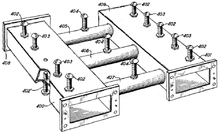
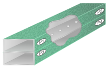
Examples can be seen in the post filter of figure 1: each cavity has a tuning screw secured with jam nuts and thread-locking compound.
[54] An iris-coupled filter consists of a cascade of impedance transformers in the form of waveguide resonant cavities coupled together by irises.
[55] Posts are conducting bars, usually circular, fixed internally across the height of the waveguide and are another means of introducing a discontinuity.
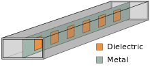
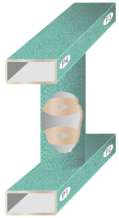
More complex patterns than the simple insert filter of figure 9 are easily achieved because the designer does not have to consider the effect on mechanical support of removing metal.
This complexity does not add to the manufacturing costs since the number of processes needed does not change when more elements are added to the design.
Tuning screws are inserted at specific intervals along the waveguide producing equivalent lumped capacitances at those points.
These capacitors resonate with the preceding length of evanescent mode waveguide which has the equivalent circuit of an inductor, thus producing a filtering action.
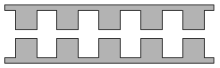
Typically, they are designed by the image parameter method with all ridges identical, but other classes of filter such as Chebyshev can be achieved in exchange for complexity of manufacture.
Higher frequencies in the unwanted band, however, readily propagate along the side guides which are terminated with a matched load where the power is absorbed.
In a frequency filter typically the parameter optimised is stopband rejection, passband attenuation, steepness of transition, or some compromise between these.
For instance the rat-race coupler (which can be implemented directly in waveguide) works on a completely different principle but still relies on certain lengths being exact in terms of λ.
[81] For diplexers dealing with contiguous passbands proper account of the crossover characteristics of filters needs to be considered in the design.