Milling cutter
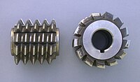
There are 8 cutters (excluding the rare half sizes) that will cut gears from 12 teeth through to a rack (infinite diameter).
A cross-section of the cutter's tooth will generate the required shape on the workpiece, once set to the appropriate conditions (blank size).
As the entire unit rotates, the tool bits take broad, shallow facing cuts.
Often these bits will be mounted at right angles to the bar's main axis, and the cutting geometry is supplied by using a standard right-hand turning tool.
However, given that a machinist can never be careless with impunity around rotating cutters or workpieces, this just means using the same care as always except with slightly higher stakes.
Well-made fly bars in conscientious hands give years of trouble-free, cost-effective service for the facing off of large polygonal workpieces such as die/mold blocks.
An advantage to using an indexable adjustable hollow mill on a Swiss-style machine is replacing multiple tools.
More advanced hollow mills use indexable carbide inserts for cutting, although traditional high speed steel and carbide-tipped blades are still used.
A hollow mill can reduce the diameter of a part and also perform facing, centering, and chamfering in a single pass.
An adjustable hollow mill is a valuable tool for even a small machine shop to have because the blades can be changed out for an almost infinite number of possible geometries.
Within the central cylindrical area, one or several socket head cap screws fasten the shell to the arbor.
As with the threaded-spindle-nose lathe chucks, this style of mounting requires that the cutter only make cuts in one rotary direction.
The radius values for each tool are entered into the offset register(s) by the CNC operator or machinist, who then tweaks them during production in order to keep the finished sizes within tolerance.
Cutter location for 3D contouring in 3-, 4-, or 5-axis milling with a ball-endmill is handled readily by CAM software rather than manual programming.
Typically the CAM vector output is postprocessed into G-code by a postprocessor program that is tailored to the particular CNC control model.
Some late-model CNC controls accept the vector output directly, and do the translation to servo inputs themselves, internally.
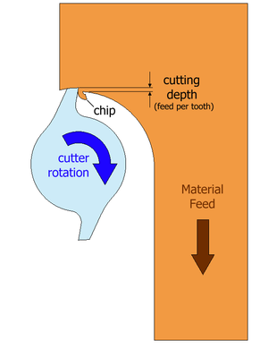
Another important quality of the milling cutter to consider is its ability to deal with the swarf generated by the cutting process.
Several factors affect swarf removal, including the depth and angle of the flutes, the size and shape of the chips, the flow of coolant, and the surrounding material.
It may be difficult to predict, but a good machinist will watch out for swarf build up, and adjust the milling conditions if it is observed.
There are many variables, opinions and lore to consider, but essentially the machinist is trying to choose a tool that will cut the material to the required specification for the least cost.
Milling evolved from rotary filing, so there is a continuum of development between the earliest milling cutters known, such as that of Jacques de Vaucanson from about the 1760s or 1770s,[3][4] through the cutters of the milling pioneers of the 1810s through 1850s (Whitney, North, Johnson, Nasmyth, and others),[5] to the cutters developed by Joseph R. Brown of Brown & Sharpe in the 1860s, which were regarded as a break from the past[6][7] for their large step forward in tooth coarseness and for the geometry that could take successive sharpenings without losing the clearance (rake, side rake, and so on).
De Vries (1910)[7] reported, "This revolution in the science of milling cutters took place in the States about the year 1870, and became generally known in Europe during the Exhibition in Vienna in 1873.
Even we ourselves can remember that after the coarse pitched cutter had been introduced, certain very clever and otherwise shrewd experts and engineers regarded the new cutting tool with many a shake of the head.
When[,] however, the Worlds Exhibition at Philadelphia in 1876, exhibited to European experts a universal and many-sided application of the coarse pitched milling cutter which exceeded even the most sanguine expectations, the most far-seeing engineers were then convinced of the immense advantages which the application of the new type opened up for the metalworking industry, and from that time onwards the American type advanced, slowly at first, but later on with rapid strides".
He also provides a citation on how the introduction of vertical mills brought about wider use of the endmill and fly cutter types.


· 10 diametral pitch cutter
· Cuts gears from 26 through to 34 teeth
· 14.5 degree pressure angle