Fraunhofer diffraction
The equation was named in honor of Joseph von Fraunhofer[3] although he was not actually involved in the development of the theory.
[4] These effects can be modelled using the Huygens–Fresnel principle; Huygens postulated that every point on a wavefront acts as a source of spherical secondary wavelets and the sum of these secondary wavelets determines the form of the proceeding wave at any subsequent time, while Fresnel developed an equation using the Huygens wavelets together with the principle of superposition of waves, which models these diffraction effects quite well.
Generally, a two-dimensional integral over complex variables has to be solved and in many cases, an analytic solution is not available.
At a sufficiently distant plane of observation from the aperture, the phase of the wave coming from each point on the aperture varies linearly with the point position on the aperture, making the calculation of the sum of the waves at an observation point on the plane of observation relatively straightforward in many cases.
[7] A diffracted wave is often called Far field if it at least partially satisfies Fraunhofer condition such that the distance between the aperture and the observation plane
– The smaller of the two distances, one is between the diffracting aperture and the plane of observation and the other is between the diffracting plane and the point wave source.For example, if a 0.5 mm diameter circular hole is illuminated by a laser light with 0.6 μm wavelength, then Fraunhofer diffraction occurs if the viewing distance is greater than 1000 mm.
The phase difference between waves propagating along the paths r2 and r1 are, with the wavenumber where λ is the light wavelength,
where L is the distance between the diffracting plane and the point wave source is satisfied, Fraunhofer condition is
So, if a positive lens with a sufficiently long focal length (so that differences between electric field orientations for wavelets can be ignored at the focus) is placed after an aperture, then the lens practically makes the Fraunhofer diffraction pattern of the aperture on its focal plane as the parallel rays meet each other at the focus.
[9] In each of these examples, the aperture is illuminated by a monochromatic plane wave at normal incidence.
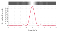
The width of the slit is W. The Fraunhofer diffraction pattern is shown in the image together with a plot of the intensity vs. angle θ.
Thus, the smaller the aperture, the larger the angle α subtended by the diffraction bands.
We can find the angle at which a first minimum is obtained in the diffracted light by the following reasoning.
The component of the wavelet emitted from the point A which is travelling in the θ direction is in anti-phase with the wave from the point B at middle of the slit, so that the net contribution at the angle θ from these two waves is zero.
We can develop an expression for the far field of a continuous array of point sources of uniform amplitude and of the same phase.
Let the array of length a be parallel to the y axis with its center at the origin as indicated in the figure to the right.
The form of the diffraction pattern given by a rectangular aperture is shown in the figure on the right (or above, in tablet format).
The Airy disk can be an important parameter in limiting the ability of an imaging system to resolve closely located objects.
The form of the function is plotted on the right (above, for a tablet), and it can be seen that, unlike the diffraction patterns produced by rectangular or circular apertures, it has no secondary rings.
[15] This technique can be used in a process called apodization—the aperture is covered by a Gaussian filter, giving a diffraction pattern with no secondary rings.
[16] In the double-slit experiment, the two slits are illuminated by a single light beam.
The fringes in the picture were obtained using the yellow light from a sodium light (wavelength = 589 nm), with slits separated by 0.25 mm, and projected directly onto the image plane of a digital camera.
Double-slit interference fringes can be observed by cutting two slits in a piece of card, illuminating with a laser pointer, and observing the diffracted light at a distance of 1 m. If the slit separation is 0.5 mm, and the wavelength of the laser is 600 nm, then the spacing of the fringes viewed at a distance of 1 m would be 1.2 mm.
If the viewing distance is large compared with the separation of the slits (the far field), the phase difference can be found using the geometry shown in the figure.
When the two waves are in phase, i.e. the path difference is equal to an integral number of wavelengths, the summed amplitude, and therefore the summed intensity is maximal, and when they are in anti-phase, i.e. the path difference is equal to half a wavelength, one and a half wavelengths, etc., then the two waves cancel, and the summed intensity is zero.
When the distance between the slits and the viewing plane is z, the spacing of the fringes is equal to zθ and is the same as above:
A grating is defined in Born and Wolf as "any arrangement which imposes on an incident wave a periodic variation of amplitude or phase, or both".
The finer the grating spacing, the greater the angular separation of the diffracted beams.
The detailed structure of the repeating pattern determines the form of the individual diffracted beams, as well as their relative intensity while the grating spacing always determines the angles of the diffracted beams.
If the light travelling at an angle θ from each slit has a path difference of one wavelength with respect to the adjacent slit, all these waves will add together, so that the maximum intensity of the diffracted light is obtained when: