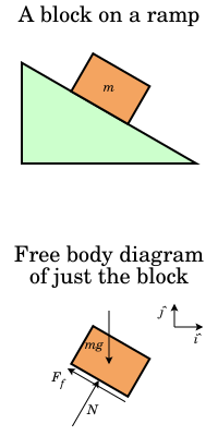
Free body diagram
In physics and engineering, a free body diagram (FBD; also called a force diagram)[1] is a graphical illustration used to visualize the applied forces, moments, and resulting reactions on a free body in a given condition.
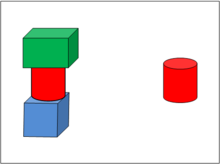
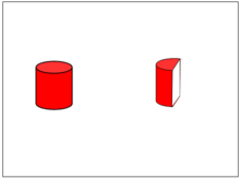
In figure 2, the interest has shifted to just the left half of the red cylinder and so now it is the free body on the right.
[4][5] In the educational environment, a free body diagram is an important step in understanding certain topics, such as statics, dynamics and other forms of classical mechanics.
[6] Free body diagrams consist of: The number of forces and moments shown depends upon the specific problem and the assumptions made.
Common assumptions are neglecting air resistance and friction and assuming rigid body action.
For example, a gymnast performing the iron cross: modeling the ropes and person allows calculation of overall forces (body weight, neglecting rope weight, breezes, buoyancy, electrostatics, relativity, rotation of the earth, etc.).
The purpose of the diagram is to help to determine magnitude, direction, and point of application of external loads.
When in a non-inertial reference frame (see coordinate system, below), fictitious forces, such as centrifugal pseudoforce are appropriate.
Judicious selection of a coordinate system can make defining the vectors simpler when writing the equations of motion or statics.
When the sum of all forces and moments is zero, the body is at rest or moving and/or rotating at a constant velocity, by Newton's first law.
Determining the sum of the forces and moments is straightforward if they are aligned with coordinate axes, but it is more complex if some are not.
It is convenient to use the components of the forces, in which case the symbols ΣFx and ΣFy are used instead of ΣF (the variable M is used for moments).
The remaining edge of the polygon O-e represents the resultant force R. In dynamics a kinetic diagram is a pictorial device used in analyzing mechanics problems when there is determined to be a net force and/or moment acting on a body.