Giant magnetoresistance
The 2007 Nobel Prize in Physics was awarded to Albert Fert and Peter Grünberg for the discovery of GMR, which also sets the foundation for the study of spintronics.
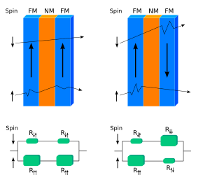
The effect is observed as a significant change in the electrical resistance depending on whether the magnetization of adjacent ferromagnetic layers are in a parallel or an antiparallel alignment.
The main application of GMR is in magnetic field sensors, which are used to read data in hard disk drives, biosensors, microelectromechanical systems (MEMS) and other devices.
[1] GMR multilayer structures are also used in magnetoresistive random-access memory (MRAM) as cells that store one bit of information.
[7][8] GMR was discovered in 1988 independently[9][10] by the groups of Albert Fert of the University of Paris-Sud, France, and Peter Grünberg of Forschungszentrum Jülich, Germany.
The practical significance of this experimental discovery was recognized by the Nobel Prize in Physics awarded to Fert and Grünberg in 2007.
[7] The enhancement of δH became possible with the advent of sample preparation techniques such as molecular beam epitaxy, which allows manufacturing multilayer thin films with a thickness of several nanometers.
[14] Fert and Grünberg studied electrical resistance of structures incorporating ferromagnetic and non-ferromagnetic materials.
Changing the thickness of the non-magnetic layers led to a significant reduction of the residual magnetization in the hysteresis loop.
The Fermi level for majority-spin electrons is located within the sp band, and their transport is similar in ferromagnets and non-magnetic metals.
The hybridized spd band has a high density of states, which results in stronger scattering and thus shorter mean free path λ for minority-spin than majority-spin electrons.
[23] According to the Drude theory, the conductivity is proportional to λ, which ranges from several to several tens of nanometers in thin metal films.
[7] The CPP geometry results in more than twice higher GMR, but is more difficult to realize in practice than the CIP configuration.
Electrons traveling through the ferromagnetic superlattice interact with it much weaker when their spin directions are opposite to the magnetization of the lattice than when they are parallel to it.
[7] Applications of the GMR effect require dynamic switching between the parallel and antiparallel magnetization of the layers in a superlattice.
[28] In 1993, Thierry Valet and Albert Fert presented a model for the giant magnetoresistance in the CPP geometry, based on the Boltzmann equations.
If the non-magnetic layer is sufficiently thin then in the external field E0 the amendments to the electrochemical potential and the field inside the sample will take the form where ℓs is the average length of spin relaxation, and the z coordinate is measured from the boundary between the magnetic and non-magnetic layers (z < 0 corresponds to the ferromagnetic).
[29] This can be represented by the potential of spin accumulation VAS or by the so-called interface resistance (inherent to the boundary between a ferromagnet and non-magnetic material) where j is current density in the sample, ℓsN and ℓsF are the length of the spin relaxation in a non-magnetic and magnetic materials, respectively.
[30] Many combinations of materials exhibit GMR;[31] the most common are the following: The magnetoresistance depends on many parameters such as the geometry of the device (CIP or CPP), its temperature, and the thicknesses of ferromagnetic and non-magnetic layers.
[38] GMR in films was first observed by Fert and Grünberg in a study of superlattices composed of ferromagnetic and non-magnetic layers.
[39] The main difference of these spin valves from other multilayer GMR devices is the monotonic dependence of the amplitude of the effect on the thickness dN of the non-magnetic layers: where δH0 is a normalization constant, λN is the mean free path of electrons in the non-magnetic material, d0 is effective thickness that includes interaction between layers.
The existence of these structures means that GMR does not require interlayer coupling, and can originate from a distribution of the magnetic moments that can be controlled by an external field.
[42] GMR in granular alloys of ferromagnetic and non-magnetic metals was discovered in 1992 and subsequently explained by the spin-dependent scattering of charge carriers at the surface and in the bulk of the grains.
A necessary condition for the GMR effect in such structures is poor mutual solubility in its components (e.g., cobalt and copper).
[32][43] One of the main applications of GMR materials is in magnetic field sensors, e.g., in hard disk drives[25] and biosensors,[31] as well as detectors of oscillations in MEMS.
When the field tends to align the magnetizations in the sensing and fixed layers, the electrical resistance of the sensor decreases, and vice versa.
The value of the stored bits can be encoded via the magnetization direction in the sensor layer; it is read by measuring the resistance of the structure.
Pulses of electric current passing through the lines generate a vortex magnetic field, which affects the GMR structure.
With the simultaneous passage of pulses along the row and column lines, of the total magnetic field at the location of the GMR structure will be directed at an acute angle with respect to one point and an obtuse to others.
TMR has now replaced GMR in MRAMs and disk drives, in particular for high area densities and perpendicular recording.