Image rectification
This process has several degrees of freedom and there are many strategies for transforming images to the common plane.
Computer stereo vision takes two or more images with known relative camera positions that show an object from different viewpoints.
However, in general settings (the camera does move towards the object or rotate) the epipolar lines are slanted.
Even with high-precision equipment, image rectification is usually performed because it may be impractical to maintain perfect coplanarity between cameras.
[2] If the images to be rectified are taken from camera pairs without geometric distortion, this calculation can easily be made with a linear transformation.
If the fundamental matrix is not known, it is necessary to find preliminary point correspondences between stereo images to facilitate its extraction.
For example, constraining the epipolar lines to be parallel with the horizontal axis means that epipoles must be mapped to the infinite point [1,0,0]T in homogeneous coordinates.
Poor choices of H and H' can result in rectified images that are dramatically changed in scale or severely distorted.
One advanced method is minimizing the disparity or least-square difference of corresponding points on the horizontal axis of the rectified image pair.
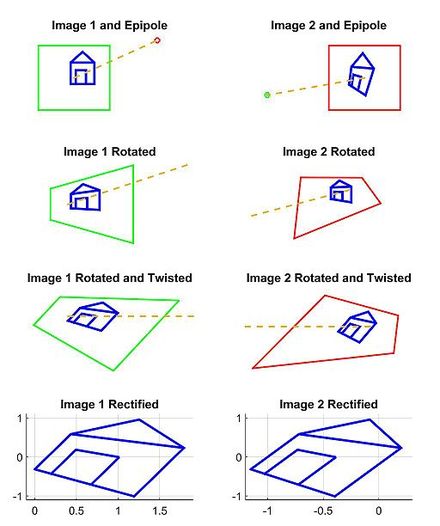
We will briefly outline and depict the results for a simple approach to find a H and H' projective transformation that rectify the image pair from the example scene.
[2] Next, we find the projective transformation H2 that takes the rotated image and twists it so that the horizontal axis aligns with the baseline.
If calculated correctly, this second transformation should map the e to infinity on the x axis (row 3, column 1 of 2D image set).
One strategy is to pick a plane parallel to the line where the two original optical axes intersect to minimize distortion from the reprojection process.
[11] Primary difficulties in the process occur The maps that are used with rectified images are non-topographical.