Inductor
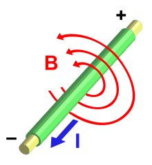
When the current flowing through the coil changes, the time-varying magnetic field induces an electromotive force (emf) (voltage) in the conductor, described by Faraday's law of induction.
According to Lenz's law, the induced voltage has a polarity (direction) which opposes the change in current that created it.
They are used to block AC while allowing DC to pass; inductors designed for this purpose are called chokes.
The term inductor seems to come from Heinrich Daniel Ruhmkorff, who called the induction coil he invented in 1851 an inductorium.
[3][4][5][6] Thus The inductance of a circuit depends on the geometry of the current path as well as the magnetic permeability of nearby materials.
induced by any change in magnetic flux through the circuit is given by[6] Reformulating the definition of L above, we obtain[6] It follows that
Thus, inductance is also a measure of the amount of electromotive force (voltage) generated for a given rate of change of current.
[8][9][10] The energy from the external circuit necessary to overcome this potential "hill" is being stored in the magnetic field of the inductor.
The quality factor (or Q) of an inductor is the ratio of its inductive reactance to its resistance at a given frequency, and is a measure of its efficiency.
Inductors are used as the energy storage device in many switched-mode power supplies to produce DC current.
A tuned circuit, consisting of an inductor connected to a capacitor, acts as a resonator for oscillating current.
Tuned circuits are widely used in radio frequency equipment such as radio transmitters and receivers, as narrow bandpass filters to select a single frequency from a composite signal, and in electronic oscillators to generate sinusoidal signals.
Two (or more) inductors in proximity that have coupled magnetic flux (mutual inductance) form a transformer, which is a fundamental component of every electric utility power grid.
The efficiency of a transformer may decrease as the frequency increases due to eddy currents in the core material and skin effect on the windings.
Real inductors are increasingly being replaced by active circuits such as the gyrator which can synthesize inductance using capacitors.
Low frequency inductors are constructed like transformers, with cores of electrical steel laminated to prevent eddy currents.
Small inductors can be etched directly onto a printed circuit board by laying out the trace in a spiral pattern.
Small value inductors can also be built on integrated circuits using the same processes that are used to make interconnects.
However, the small dimensions limit the inductance, and it is far more common to use a circuit called a gyrator that uses a capacitor and active components to behave similarly to an inductor.
The term refers to coils wound on plastic, ceramic, or other nonmagnetic forms, as well as those that have only air inside the windings.
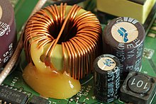
Ferromagnetic-core or iron-core inductors use a magnetic core made of a ferromagnetic or ferrimagnetic material such as iron or ferrite to increase the inductance.
However the magnetic properties of the core material cause several side effects which alter the behavior of the inductor and require special construction: Low-frequency inductors are often made with laminated cores to prevent eddy currents, using construction similar to transformers.
The core is made of stacks of thin steel sheets or laminations oriented parallel to the field, with an insulating coating on the surface.
[24] Probably the most common type of variable inductor today is one with a moveable ferrite magnetic core, which can be slid or screwed in or out of the coil.
Air core inductors can use sliding contacts or multiple taps to increase or decrease the number of turns included in the circuit, to change the inductance.
A type much used in the past but mostly obsolete today has a spring contact that can slide along the bare surface of the windings.
These turns act like a single-turn short-circuited transformer secondary winding; the large currents induced in them cause power losses.
A choke is an inductor designed specifically for blocking high-frequency alternating current (AC) in an electrical circuit, while allowing DC or low-frequency signals to pass.
To find their total inductance: These simple relationships hold true only when there is no mutual coupling of magnetic fields between individual inductors.
The table below lists some common simplified formulas for calculating the approximate inductance of several inductor constructions.