Variable-frequency drive
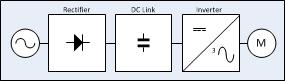
[14] The VFD controller is a solid-state power electronics conversion system consisting of three distinct sub-systems: a rectifier bridge converter, a direct current (DC) link, and an inverter.
The most basic rectifier converter for the VSI drive is configured as a three-phase, six-pulse, full-wave diode bridge.
[15] Controller advances have exploited dramatic increases in the voltage and current ratings and switching frequency of solid-state power devices over the past six decades.
Introduced in 1983,[16] the insulated-gate bipolar transistor (IGBT) has in the past two decades come to dominate VFDs as an inverter switching device.
Some V/Hz control drives can also operate in quadratic V/Hz mode or can even be programmed to suit special multi-point V/Hz paths.
Although space vector pulse-width modulation (SVPWM) is becoming increasingly popular,[23] sinusoidal PWM (SPWM) is the most straightforward method used to vary drives' motor voltage (or current) and frequency.
User programming of display, variable, and function block parameters is provided to control, protect, and monitor the VFD, motor, and driven equipment.
An operator interface keypad and display unit is often provided on the front of the VFD controller as shown in the photograph above.
Most are also provided with input and output (I/O) terminals for connecting push buttons, switches, and other operator interface devices or control signals.
Referring to the accompanying chart, drive applications can be categorized as single-quadrant, two-quadrant, or four-quadrant; the chart's four quadrants are defined as follows:[32][33][34] Most applications involve single-quadrant loads operating in quadrant I, such as in variable-torque (e.g. centrifugal pumps or fans) and certain constant-torque (e.g. extruders) loads.
Certain applications involve two-quadrant loads operating in quadrant I and II where the speed is positive but the torque changes polarity as in case of a fan decelerating faster than natural mechanical losses.
Some sources define two-quadrant drives as loads operating in quadrants I and III where the speed and torque is same (positive or negative) polarity in both directions.
Certain high-performance applications involve four-quadrant loads (Quadrants I to IV) where the speed and torque can be in any direction such as in hoists, elevators, and hilly conveyors.
After the start of the VFD, the applied frequency and voltage are increased at a controlled rate or ramped up to accelerate the load.
A small amount of braking torque is available to help decelerate the load a little faster than it would stop if the motor were simply switched off and allowed to coast.
With a four-quadrant rectifier (active front-end), the VFD is able to brake the load by applying a reverse torque and injecting the energy back to the AC line.
Many fixed-speed motor load applications that are supplied direct from AC line power can save energy when they are operated at variable speed by means of VFD.
Such energy cost savings are especially pronounced in variable-torque centrifugal fan and pump applications, where the load's torque and power vary with the square and cube, respectively, of the speed.
In the United States, an estimated 60–65% of electrical energy is used to supply motors, 75% of which are variable-torque fan, pump, and compressor loads.
[42] An energy consumption breakdown of the global population of AC motor installations is as shown in the following table: AC drives are used to bring about process and quality improvements in industrial and commercial applications' acceleration, flow, monitoring, pressure, speed, temperature, tension, and torque.
Performance factors tending to favor the use of DC drives over AC drives include such requirements as continuous operation at low speed, four-quadrant operation with regeneration, frequent acceleration and deceleration routines, and need for the motor to be protected for a hazardous area.
When the power company's voltage becomes distorted due to harmonics, losses in other loads such as normal fixed-speed AC motors are increased.
In high-power installations, harmonic distortion can be reduced by supplying multi-pulse rectifier-bridge VFDs from transformers with multiple phase-shifted windings.
With PWM control and a suitable input reactor, an AFE's AC line current waveform can be nearly sinusoidal.
[73] It is very common practice for power companies or their customers to impose harmonic distortion limits based on IEC or IEEE standards.
For example, IEEE Standard 519 limits at the customer's connection point call for the maximum individual frequency voltage harmonic to be no more than 3% of the fundamental and call for the voltage total harmonic distortion (THD) to be no more than 5% for a general AC power supply system.
A carrier frequency in the range of 2,000 to 16,000 Hz is common for LV [low voltage, under 600 Volts AC] VFDs.
For emerging SiC MOSFET powered drives, significant overvoltages have been observed at cable lengths as short as 3 meters.
[77] Solutions to overvoltages caused by long lead lengths include minimizing cable length, lowering carrier frequency, installing dV/dt filters, using inverter-duty-rated motors (that are rated 600 V to withstand pulse trains with rise time less than or equal to 0.1 microsecond, of 1,600 V peak magnitude), and installing LCR low-pass sine wave filters.
[86] PWM drives are inherently associated with high-frequency common-mode voltages and currents which may cause trouble with motor bearings.