Infinite impulse response
Common examples of linear time-invariant systems are most electronic and digital filters.
In practice, the impulse response, even of IIR systems, usually approaches zero and can be neglected past a certain point.
However the physical systems which give rise to IIR or FIR responses are dissimilar, and therein lies the importance of the distinction.
The capacitors (or inductors) in the analog filter have a "memory" and their internal state never completely relaxes following an impulse (assuming the classical model of capacitors and inductors where quantum effects are ignored).
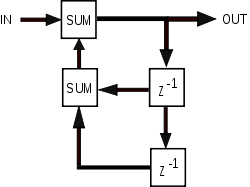
The presence of feedback in the topology of a discrete-time filter (such as the block diagram shown below) generally creates an IIR response.
The z domain transfer function of an IIR filter contains a non-trivial denominator, describing those feedback terms.
The transfer function of an FIR filter, on the other hand, has only a numerator as expressed in the general form derived below.
The transfer functions pertaining to IIR analog electronic filters have been extensively studied and optimized for their amplitude and phase characteristics.
These continuous-time filter functions are described in the Laplace domain.
Desired solutions can be transferred to the case of discrete-time filters whose transfer functions are expressed in the z domain, through the use of certain mathematical techniques such as the bilinear transform, impulse invariance, or pole–zero matching method.
Digital filters are often described and implemented in terms of the difference equation that defines how the output signal is related to the input signal: where: A more condensed form of the difference equation is: To find the transfer function of the filter, we first take the Z-transform of each side of the above equation to obtain: After rearranging: We then define the transfer function to be: The transfer function allows one to judge whether or not a system is bounded-input, bounded-output (BIBO) stable.
To be specific, the BIBO stability criterion requires that the ROC of the system includes the unit circle.
For example, for a causal system, all poles of the transfer function have to have an absolute value smaller than one.
This is in contrast to the FIR filter where all poles are located at the origin, and is therefore always stable.
The main advantage digital IIR filters have over FIR filters is their efficiency in implementation, in order to meet a specification in terms of passband, stopband, ripple, and/or roll-off.
If implemented in a signal processor, this implies a correspondingly fewer number of calculations per time step; the computational savings is often of a rather large factor.
On the other hand, FIR filters can be easier to design, for instance, to match a particular frequency response requirement.
This is particularly true when the requirement is not one of the usual cases (high-pass, low-pass, notch, etc.)
Another issue regarding digital IIR filters is the potential for limit cycle behavior when idle, due to the feedback system in conjunction with quantization.
Impulse invariance is one of the commonly used methods to meet the two basic requirements of the mapping from the s-plane to the z-plane.
This is obtained by solving the T(z) that has the same output value at the same sampling time as the analog filter, and it is only applicable when the inputs are in a pulse.
When applying the Laplace transform or z-transform on the unit impulse, the result is 1.
It can also be expressed as y(n) This discrete time signal can be applied z-transform to get T(z) The last equation mathematically describes that a digital IIR filter is to perform z-transform on the analog signal that has been sampled and converted to T(s) by Laplace, which is usually simplified to Pay attention to the fact that there is a multiplier T appearing in the formula.
The digital filter has several segments of input with different constants when sampling, which is composed of discrete steps.
Apply z-transform and Laplace transform on these two inputs to obtain the converted output signal.
The following equation points out the solution of T(z), which is the approximate formula for the analog filter.
The bilinear transform is a special case of a conformal mapping, often used to convert a transfer function
The bilinear transform is a first-order approximation of the natural logarithm function that is an exact mapping of the z-plane to the s-plane.
is the numerical integration step size of the trapezoidal rule used in the bilinear transform derivation; or, in other words, the sampling period.
The bilinear transform essentially uses this first order approximation and substitutes into the continuous-time transfer function,