LED circuit
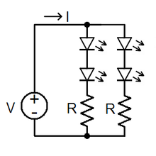
With a sufficiently high supply voltage, multiple LEDs in series can be powered with one resistor.
If the voltage is below or equal to the threshold no current flows and the result is an unlit LED.
If the voltage is too high, the current will exceed the maximum rating, overheating and potentially destroying the LED.
An active constant current source is commonly used for high power LEDs, stabilizing light output over a wide range of input voltages which might increase the useful life of batteries.
Power integrated circuit (IC) chips are widely used to drive the MOSFETs directly, without the need for additional circuitry.
Miniature indicator LEDs are normally driven from low voltage DC via a current-limiting resistor.
Sub-mA indicators may be made by driving ultra-bright LEDs at very low current.
Efficiency tends to reduce at low currents,[3] but indicators running on 100 μA are still practical.
These may save printed circuit board space, and are especially useful when building prototypes or populating a PCB in a way other than its designers intended.
The value for the series resistance may be obtained from Ohm's law, considering that the supply voltage is offset by the diode's
is 0 (to simplify examples), the resistance is calculated as follows: Strings of multiple LEDs are normally connected in series.
Variations in the manufacturing process can make it difficult to obtain satisfactory operation when connecting some types of LEDs in parallel.
However, multiplexed display techniques are more often used than direct drive, because they have lower net hardware costs.
The clock scans through the digits rapidly enough that it gives the illusion that it is "constantly" displaying "12:34" for an entire minute.
An extension of this technique is Charlieplexing where the ability of some microcontrollers to tri-state their output pins means larger numbers of LEDs can be driven, without using latches.
The use of integrated circuit technology to drive LEDs dates back to the late 1960s.
When the voltage across the p-n junction is in the correct direction, a significant current flows and the device is said to be forward-biased.
If the voltage is of the wrong polarity, the device is said to be reverse biased, very little current flows, and no light is emitted.
[3][9] Most LED data sheets specify a maximum DC current that is safe for continuous operation.
This capability may be used in a variety of applications including ambient light detection and bidirectional communications.