Joule thief
This self-stroking/positive-feedback process almost instantly turns the transistor on as hard as possible (putting it in the saturation region), making the collector-emitter path look like essentially a closed switch (since VCE will be only about 0.1 volts, assuming that the base current is high enough).
With the primary winding effectively across the battery, the current increases at a rate proportional to the supply voltage divided by the inductance.
Hence, when it reaches a critical collector current, the base drive available becomes insufficient and the transistor starts to pinch off and the previously described positive feedback action occurs turning it hard off.
To summarize, once the current in the coils stops increasing for any reason, the transistor goes into the cutoff region (and opens the collector-emitter "switch").
The magnetic field collapses, inducing however much voltage is necessary to make the load conduct, or for the secondary-winding current to find some other path.
As there is no regulation, any excess of energy not consumed by the load, will be dissipated as heat in the zener diode with consequent low efficiency of conversion.
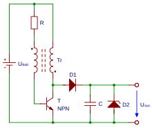
In the example circuit, the Schottky diode D1 blocks the charge built up on capacitor C1 from flowing back to the switching transistor Q1 when it is turned on.