Fatigue (material)
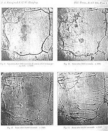
Once a fatigue crack has initiated, it grows a small amount with each loading cycle, typically producing striations on some parts of the fracture surface.
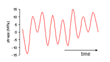
[2] To aid in predicting the fatigue life of a component, fatigue tests are carried out using coupons to measure the rate of crack growth by applying constant amplitude cyclic loading and averaging the measured growth of a crack over thousands of cycles.
[2] If the loads are above a certain threshold, microscopic cracks will begin to initiate at stress concentrations such as holes, persistent slip bands (PSBs), composite interfaces or grain boundaries in metals.
The formation of initial cracks preceding fatigue failure is a separate process consisting of four discrete steps in metallic samples.
These newly formed cell structures will eventually break down with the formation of persistent slip bands (PSBs).
It is for this reason that cyclic fatigue failures seem to occur so suddenly where the bulk of the changes in the material are not visible without destructive testing.
The following effects change the rate of growth:[2] The American Society for Testing and Materials defines fatigue life, Nf, as the number of stress cycles of a specified character that a specimen sustains before failure of a specified nature occurs.
[25] However, in practice, several bodies of work done at greater numbers of cycles suggest that fatigue limits do not exist for any metals.
[26][27][28] Engineers have used a number of methods to determine the fatigue life of a material:[29] Whether using stress/strain-life approach or using crack growth approach, complex or variable amplitude loading is reduced to a series of fatigue equivalent simple cyclic loadings using a technique such as the rainflow-counting algorithm.
This can be thought of as assessing what proportion of life is consumed by a linear combination of stress reversals at varying magnitudes.
A Constant Fatigue Life (CFL) diagram is useful for stress ratio effect on S-N curve.
[35] Also, in the presence of a steady stress superimposed on the cyclic loading, the Goodman relation can be used to estimate a failure condition.
With face-centered cubic metals (fcc), the Wöhler curve generally drops continuously, so that only a fatigue limit can be assigned to these materials.
Safety or scatter factors are applied to the calculated life to account for any uncertainty and variability associated with fatigue.
For normal manufacturing finishes this may cover most of the fatigue life of a component where growth can start from the first cycle.
[54] In addition, the unique joints and attachments used for composite structures often introduce modes of failure different from those typified by the laminate itself.
In many cases, the damage rate is accelerated by deleterious interactions with the environment like oxidation or corrosion of fibers.
[56] Following the King Louis-Philippe I's celebrations at the Palace of Versailles, a train returning to Paris crashed in May 1842 at Meudon after the leading locomotive broke an axle.
At least 55 passengers were killed trapped in the locked carriages, including the explorer Jules Dumont d'Urville.
Rankine's investigation of broken axles in Britain highlighted the importance of stress concentration, and the mechanism of crack growth with repeated loading.
His and other papers suggesting a crack growth mechanism through repeated stressing, however, were ignored, and fatigue failures occurred at an ever-increasing rate on the expanding railway system.
After the equivalent of 3,000 flights, investigators at the Royal Aircraft Establishment (RAE) were able to conclude that the crash had been due to failure of the pressure cabin at the forward Automatic Direction Finder window in the roof.
This 'window' was in fact one of two apertures for the aerials of an electronic navigation system in which opaque fibreglass panels took the place of the window 'glass'.
The failure was a result of metal fatigue caused by the repeated pressurisation and de-pressurisation of the aircraft cabin.
In addition, it was discovered that the stresses around pressure cabin apertures were considerably higher than had been anticipated, especially around sharp-cornered cut-outs, such as windows.
As a result, all future jet airliners would feature windows with rounded corners, greatly reducing the stress concentration.
Investigators from the RAE told a public inquiry that the sharp corners near the Comets' window openings acted as initiation sites for cracks.
Alexander L. Kielland was a Norwegian semi-submersible drilling rig that capsized whilst working in the Ekofisk oil field in March 1980, killing 123 people.
In driving rain and mist, early in the evening of 27 March 1980 more than 200 men were off duty in the accommodation on Alexander L. Kielland.
Further, the investigation found considerable amounts of lamellar tearing in the flange plate and cold cracks in the butt weld.