Peripheral Component Interconnect
Outside the server market, the 64-bit version of plain PCI remained rare in practice though,[13] although it was used for example by all (post-iMac) G3 and G4 Power Macintosh computers.
[citation needed] PCI provides separate memory and memory-mapped I/O port address spaces for the x86 processor family, 64 and 32 bits, respectively.
The timer starts when the device gains bus ownership, and counts down at the rate of the PCI clock.
Platform-specific firmware or operating system code is meant to know this, and set the "interrupt line" field in each device's configuration space indicating which IRQ it is connected to.
In this system, a device signals its need for service by performing a memory write, rather than by asserting a dedicated line.
Finally, because the message signaling is in-band, it resolves some synchronization problems that can occur with posted writes and out-of-band interrupt lines.
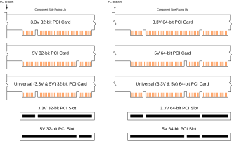
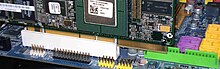
[16][18][19] 64-bit PCI extends this by an additional 32 contacts on each side which provide AD[63:32], C/BE[7:4]#, the PAR64 parity signal, and a number of power and ground pins.
Many 64-bit PCI-X cards are designed to work in 32-bit mode if inserted in shorter 32-bit connectors, with some loss of performance.
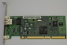
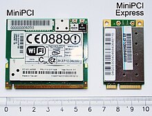
The additional 24 pins provide the extra signals required to route I/O back through the system connector (audio, AC-Link, LAN, phone-line interface).
These cards must be located at the edge of the computer or docking station so that the RJ11 and RJ45 ports can be mounted for external access.
The PCI standard explicitly allows a data phase with no bytes enabled, which must behave as a no-op.
PCI devices therefore generally attempt to avoid using the all-ones value in important status registers, so that such an error can be easily detected by software.
In this case, writes that were presented to the bus bridge in a particular order are merged so they occur at the same time when forwarded.
The PCI bus protocol is designed so this is rarely a limitation; only in a few special cases (notably fast back-to-back transactions) is it necessary to insert additional delay to meet this requirement.
To ensure that only one transaction is initiated at a time, each master must first wait for a bus grant signal, GNT#, from an arbiter located on the motherboard.
This is known as master abort termination and it is customary for PCI bus bridges to return all-ones data (0xFFFFFFFF) in this case.
PCI devices, therefore, are generally designed to avoid using the all-ones value in important status registers, so that such an error can be easily detected by software.
In case of a write, the asserted signals indicate which of the four bytes on the AD bus are to be written to the addressed location.
A data phase with all four C/BE# lines deasserted is explicitly permitted by the PCI standard, and must have no effect on the target other than to advance the address in the burst access in progress.
To maintain full burst speed, the data sender then has half a clock cycle after seeing both IRDY# and TRDY# asserted to drive the next word onto the AD bus.
A target that supports fast DEVSEL could in theory begin responding to a read on the cycle after the address is presented.
The initiator can mark any data phase as the final one in a transaction by deasserting FRAME# at the same time as it asserts IRDY#.
The cycle after the target asserts TRDY#, the final data transfer is complete, both sides deassert their respective RDY# signals, and the bus is idle again.
There are several ways for the target to do this: It will always take at least one cycle for the initiator to notice a target-initiated disconnection request and respond by deasserting FRAME#.
This is the highest-possible speed four-word write burst, terminated by the master: On clock edge 1, the initiator starts a transaction by driving an address, command, and asserting FRAME# The other signals are idle (indicated by ^^^), pulled high by the motherboard's pull-up resistors.
The PCI bus detects parity errors, but does not attempt to correct them by retrying operations; it is purely a failure indication.
An initiator may only perform back-to-back transactions when: Additional timing constraints may come from the need to turn around are the target control lines, particularly DEVSEL#.
The REQ64# and ACK64# lines are held asserted for the entire transaction save the last data phase and deasserted at the same time as FRAME# and DEVSEL#, respectively.
A coherence-supporting target would avoid completing a data phase (asserting TRDY#) until it observed SDONE high.
This would signal the active target to assert STOP# rather than TRDY#, causing the initiator to disconnect and retry the operation later.