Rotary encoder
[7] An incremental encoder will immediately report changes in position, which is an essential capability in some applications.
As a result, the mechanical system monitored by an incremental encoder may have to be homed (moved to a fixed reference point) to initialize absolute position measurements.
Brush-type contacts are susceptible to wear, and consequently mechanical encoders are typically found in low-speed applications such as manual volume or tuning controls in a radio receiver.
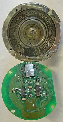
A light source and photo detector array reads the optical pattern that results from the disc's position at any one time.
This code can be read by a controlling device, such as a microprocessor or microcontroller to determine the angle of the shaft.
This code can be read by a controlling device, such as a microprocessor or microcontroller to determine the angle of the shaft, similar to an optical encoder.
In such cases, the encoder serves as a feedback device that plays a vital role in proper equipment operation.
Brushless motors require electronic commutation, which often is implemented in part by using rotor magnets as a low-resolution absolute encoder (typically six or twelve pulses per revolution).
The resulting shaft angle information is conveyed to the servo drive to enable it to energize the proper stator winding at any moment in time.
This principle, introduced in 2007,[11] uses a Wiegand sensor to produce electricity sufficient to power the encoder and write the turns count to non-volatile memory.
However, this has the drawback that if the disc stops between two adjacent sectors, or the contacts are not perfectly aligned, it can be impossible to determine the angle of the shaft.
If the designer moves a contact to a different angular position (but at the same distance from the center shaft), then the corresponding "ring pattern" needs to be rotated the same angle to give the same output.
Depending on the device and manufacturer, an absolute encoder may use any of several signal types and communication protocols to transmit data, including parallel binary, analog signals (current or voltage), and serial bus systems such as SSI, BiSS, Heidenhain EnDat, Sick-Stegmann Hiperface, DeviceNet, Modbus, Profibus, CANopen and EtherCAT, which typically employ Ethernet or RS-422/RS-485 physical layers.
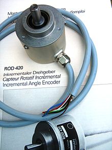
A rotary incremental encoder may use mechanical, optical or magnetic sensors to detect rotational position changes.
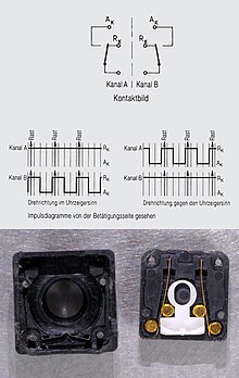
The mechanical type is commonly employed as a manually operated "digital potentiometer" control on electronic equipment.
For example, modern home and car stereos typically use mechanical rotary encoders as volume controls.
Encoders with mechanical sensors require switch debouncing and consequently are limited in the rotational speeds they can handle.
Some rotary incremental encoders have an additional "index" output (typically labeled Z), which emits a pulse when the shaft passes through a particular angle.
This is commonly used in radar systems and other applications that require a registration signal when the encoder shaft is located at a particular reference angle.