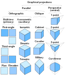
Orthographic projection
The transformation above can be represented for homogeneous coordinates as For each homogeneous vector v = (vx, vy, vz, 1), the transformed vector Pv would be In computer graphics, one of the most common matrices used for orthographic projection can be defined by a 6-tuple, (left, right, bottom, top, near, far), which defines the clipping planes.
[2][4] Typically in axonometric drawing, as in other types of pictorials, one axis of space is shown to be vertical.
In isometric projection, the most commonly used form of axonometric projection in engineering drawing,[5] the direction of viewing is such that the three axes of space appear equally foreshortened, and there is a common angle of 120° between them.
As the distortion caused by foreshortening is uniform, the proportionality between lengths is preserved, and the axes share a common scale; this eases one's ability to take measurements directly from the drawing.
In dimetric projection, the direction of viewing is such that two of the three axes of space appear equally foreshortened, of which the attendant scale and angles of presentation are determined according to the angle of viewing; the scale of the third direction is determined separately.
In trimetric projection, the direction of viewing is such that all of the three axes of space appear unequally foreshortened.
The views are positioned relative to each other according to either of two schemes: first-angle or third-angle projection.
In each, the appearances of views may be thought of as being projected onto planes that form a six-sided box around the object.
Although six different sides can be drawn, usually three views of a drawing give enough information to make a three-dimensional object.
A typical characteristic of multiview projection is that one axis of space is usually displayed as vertical.
It depicts a hemisphere of the globe as it appears from outer space, where the horizon is a great circle.
Hipparchus used the projection in the 2nd century BC to determine the places of star-rise and star-set.
In about 14 BC, Roman engineer Marcus Vitruvius Pollio used the projection to construct sundials and to compute sun positions.
[7] Vitruvius also seems to have devised the term orthographic – from the Greek orthos ("straight") and graphē ("drawing") – for the projection.
However, the name analemma, which also meant a sundial showing latitude and longitude, was the common name until François d'Aguilon of Antwerp promoted its present name in 1613.
[7] The earliest surviving maps on the projection appear as woodcut drawings of terrestrial globes of 1509 (anonymous), 1533 and 1551 (Johannes Schöner), and 1524 and 1551 (Apian).