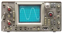
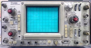
Oscilloscope
An oscilloscope, (formerly known as an oscillograph), (informally scope or O-scope) is a type of electronic test instrument that graphically displays varying voltages of one or more signals as a function of time.
Special-purpose oscilloscopes may be used to analyze an automotive ignition system or to display the waveform of the heartbeat as an electrocardiogram, for instance.Early high-speed visualisations of electrical voltages were made with an electro-mechanical oscillograph,[2][3] invented by André Blondel in 1893.
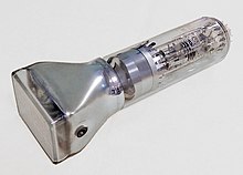
These gave valuable insights into high speed voltage changes, but had a frequency response in single kHz, and were superseded by the oscilloscope which used a cathode-ray tube (CRT) as its display element.
This results in a 0.1 (‑10×) attenuation factor; this helps to isolate the capacitive load presented by the probe cable from the signal being measured.
In addition to portable units, the market offers a number of miniature battery-powered instruments for field service applications.
Laboratory grade oscilloscopes, especially older units that use vacuum tubes, are generally bench-top devices or are mounted on dedicated carts.
A typical probe uses a 9 megohm series resistor shunted by a low-value capacitor to make an RC compensated divider with the cable capacitance and scope input.
[clarification needed] In that time frame, the cable looks like its characteristic impedance, and reflections from the transmission line mismatch at the scope input and the probe causes ringing.
Historically, some auto-sensing circuitry used indicator lamps behind translucent windows in the panel to illuminate different parts of the sensitivity scale.
These have a large probe body, and some require partly filling a canister surrounding the series resistor with volatile liquid fluorocarbon to displace air.
(Observing a high voltage ramp can create a staircase waveform with steps at different points every repetition, until the probe tip is in contact.
On flat panels, however, trace brightness is essentially independent of sweep speed, because the internal signal processing effectively synthesizes the display from the digitized data.
In all but the least-costly modern oscilloscopes, the sweep speed is selectable and calibrated in units of time per major graticule division.
However, when the signal has a fixed offset of interest, or changes slowly, the user will usually prefer "DC" coupling, which bypasses any such capacitor.
It is used to set the no-input trace exactly on the center line of the graticule, but also permits offsetting vertically by a limited amount.
This control also moves the X-Y mode traces sidewise in some instruments, and can compensate for a limited DC component as for vertical position.
To display events with unchanging or slowly (visibly) changing waveforms, but occurring at times that may not be evenly spaced, modern oscilloscopes have triggered sweeps.
For a period of time, called holdoff, (extendable by a front-panel control on some better oscilloscopes), the sweep circuit resets completely and ignores triggers.
In some cases, variable holdoff time can be useful to make the sweep ignore interfering triggers that occur before the events to be observed.
At extreme ratios, jitter in the delays on consecutive main sweeps degrades the display, but delayed-sweep triggers can overcome this.
Another combination mode multiplexes (alternates) the main and delayed sweeps so that both appear at once; a trace separation control displaces them.
Others had two complete electron guns, requiring tight control of axial (rotational) mechanical alignment in manufacturing the CRT.
This is very frequently used in broadcast engineering to plot the left and right stereophonic channels, to ensure that the stereo generator is calibrated properly.
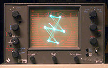
Historically, stable Lissajous figures were used to show that two sine waves had a relatively simple frequency relationship, a numerically-small ratio.
[12] Complete loss of signal in an X-Y CRT display means that the beam is stationary, striking a small spot.
This was originally achieved with a special CRT, a storage tube, which retained the image of even a very brief event for a long time.
Since most failures occur because of a single faulty component, each measurement can show that some of the stages of a complex piece of equipment either work, or probably did not cause the fault.
This sort of troubleshooting is typical of radio and TV receivers, as well as audio amplifiers, but can apply to quite different devices such as electronic motor drives.
Storage allows a trace pattern that normally would decay in a fraction of a second to remain on the screen for several minutes or longer.
This type of DSO deliberately samples at a much lower frequency than the Nyquist limit and then uses signal processing to reconstruct a composite view of a typical pulse.