Pelton wheel
At this time many mining operations were powered by steam engines which consumed vast amounts of wood as their fuel.
Some water wheels were used in the larger rivers, but they were ineffective in the smaller streams that were found near the mines.
In 1876, he approached the Miners Foundry in Nevada City, California to build the first commercial models in iron.
[4] The efficiency advantages of Pelton's invention were quickly recognized and his product was soon in high demand.
In 1892, the Company added a branch on the east coast at 143 Liberty Street in New York City.
In 1914, the company moved manufacturing to new, larger premises at 612 Alabama Street in San Francisco.
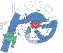
Nozzles direct forceful, high-speed streams of water against a series of spoon-shaped buckets, also known as impulse blades, which are mounted around the outer rim of a drive wheel (also called a runner).
"[7] Pelton wheels are the preferred turbine for hydro-power where the available water source has relatively high hydraulic head at low flow rates.
There exist multi-ton Pelton wheels mounted on vertical oil pad bearings in hydroelectric plants.
The largest units – the Bieudron Hydroelectric Power Station at the Grande Dixence Dam complex in Switzerland – are over 400 megawatts.
[8] The smallest Pelton wheels are only a few inches across, and can be used to tap power from mountain streams having flows of a few gallons per minute.
These small units are recommended for use with 30 metres (100 ft) or more of head, in order to generate significant power levels.
Depending on water flow and design, Pelton wheels operate best with heads from 15–1,800 metres (50–5,910 ft), although there is no theoretical limit.
[citation needed] Such "peltric sets", consisting of a Pelton wheel, an induction generator and a control mechanism, are used in Nepal.
(dimensionless parameter), [10] where: The formula implies that the Pelton turbine is geared most suitably for applications with relatively high hydraulic head H, due to the 5/4 exponent being greater than unity, and given the characteristically low specific speed of the Pelton.
Note the minus sign indicates the reduction in stream velocity from impacting the runner.
For the stationary runner case, the stream velocity is -Vf, indicating the fluid fully reversed direction.
In this case the force on the wheel is the highest (due to the largest possible velocity change), but power delivered is zero, since there is no movement.
To find the runner speed at maximum power, take the derivative of P with respect to u and set it equal to zero, [dP/du = 2ρQ(Vi − 2u)].
Originally the penstock was the name of the valve, but the term has been extended to include all of the fluid supply hydraulics.
Penstock is now used as a general term for a water passage and control that is under pressure, whether it supplies an impulse turbine or not.