Radar cross section
For example, a stealth aircraft (which is designed to have low detectability) will have design features that give it a low RCS (such as absorbent paint, flat surfaces, surfaces specifically angled to reflect the signal somewhere other than towards the source), as opposed to a passenger airliner that will have a high RCS (bare metal, rounded surfaces effectively guaranteed to reflect some signal back to the source, many protrusions like the engines, antennas, etc.).
RCS is integral to the development of radar stealth technology, particularly in applications involving aircraft and ballistic missiles.
term represents isotropic spreading of this intercepted power from the target back to the radar receiver.
represents the reflected power density at the radar receiver (again watts per meter squared).
In this light, RCS can be viewed as a correction factor that makes the radar equation "work out right" for the experimentally observed ratio of
For example, 10 cm (S-band radar) can detect rain drops but not clouds whose droplets are too small.
Wood and cloth (such as portions of airplanes and balloons used to be commonly made) or plastic and fibreglass are less reflective or indeed transparent to radar making them suitable for radomes.
The edges are sharp to prevent rounded surfaces which are normal at some point to the radar source.
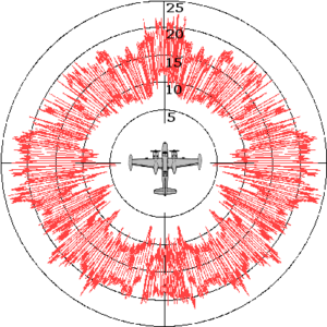
All other factors being equal, the aircraft will have a stronger signal from the side than from the front; hence the orientation of the target relative to the radar station is important.
This could arise from open bomb-bays, engine intakes, ordnance pylons, joints between constructed sections, etc.
If the RCS was directly related to the target's cross-sectional area, the only way to reduce it would be to make the physical profile smaller.
Rather, by reflecting much of the radiation away or by absorbing it, the target achieves a smaller radar cross section.
Such a range eliminates the need for placing radar absorbers behind the target, however multi-path interactions with the ground must be mitigated.
In such a room, the target is placed on a rotating pillar in the center, and the walls, floors and ceiling are covered by stacks of radar absorbing material.
In the design phase, it is often desirable to employ a computer to predict what the RCS will look like before fabricating an actual object.
Many iterations of this prediction process can be performed in a short time at low cost, whereas use of a measurement range is often time-consuming, expensive and error-prone.
The linearity of Maxwell's equations makes RCS relatively straightforward to calculate with a variety of analytic and numerical methods, but changing levels of military interest and the need for secrecy have made the field challenging, nonetheless.
The field of solving Maxwell's equations through numerical algorithms is called computational electromagnetics, and many effective analysis methods have been applied to the RCS prediction problem.
RCS prediction software are often run on large supercomputers and employ high-resolution CAD models of real radar targets.
RCS reduction is chiefly important in stealth technology for aircraft, missiles, ships, and other military vehicles.
The distance at which a target can be detected for a given radar configuration varies with the fourth root of its RCS.
While this degree of improvement is challenging, it is often possible when influencing platforms during the concept/design stage and using experts and advanced computer code simulations to implement the control options described below.
This aircraft, designed in the late 1970s though only revealed to the public in 1988, uses a multitude of flat surfaces to reflect incident radar energy away from the source.
Yue suggests[13] that limited available computing power for the design phase kept the number of surfaces to a minimum.
The B-2 Spirit stealth bomber benefited from increased computing power, enabling its contoured shapes and further reduction in RCS.
The F-22 Raptor and F-35 Lightning II continue the trend in purpose shaping and promise to have even smaller monostatic RCS.
[14][15][16] As mentioned earlier, the primary objective in geometry alteration is to redirect scattered waves away from the backscattered direction (or the source).
[14][15][17] One feasible solution, which has extensively been explored in recent time, is to utilize metasurfaces which can redirect scattered waves without altering the geometry of the target.
Except against simple or low frequency radar systems, the implementation of active cancellation techniques is extremely difficult due to the complex processing requirements and the difficulty of predicting the exact nature of the reflected radar signal over a broad aspect of an aircraft, missile or other target.
Radar absorbent material (RAM)[2] can be used in the original construction, or as an addition to highly reflective surfaces.