Low-frequency radio range
It soon became apparent that for reliable mail delivery, as well as the passenger flights which were soon to follow, a solution was required for navigation at night and in poor visibility.
[8][9] Doolittle used newly developed gyroscopic instruments—attitude indicator and gyrocompass—to help him maintain his aircraft's attitude and heading, and a specially designed directional radio system to navigate to and from the airport.
[10][note 1] Doolittle's experimental equipment was purpose-built for his demonstration flights; for instrument flying to become practical, the technology had to be reliable, mass-produced and widely deployed, both on the ground and in the aircraft fleet.
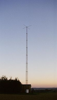
On the ground, to obtain directional radio beams with a well-defined navigable course, crossed loop antennas were used initially.
The technology was quickly adopted by the U.S. Commerce Department, who set up a demonstration range on June 30, 1928,[2][7] and the first series of stations entered service later that year.
Low-frequency radio transmitters provided navigational guidance to aircraft for en route operations and approaches under virtually all weather conditions, helping to make consistent and reliable flight schedules a reality.
[note 3] The intersections between the quadrants defined four course lines emanating from the transmitting station, along four compass directions, where the A and N signals were of equal intensity, with their combined Morse codes merging into a steady 1,020 Hz audio tone.
[3][note 4] Also, in some installations local weather conditions were periodically broadcast in voice over the range frequency, preempting the navigational signals, but eventually this was done on the central fifth tower.
[4] Pilots had to verify that they were tuned to the correct range station frequency by comparing its Morse code identifier against the one published on their navigation charts.
This quiet zone, called the "cone of silence", signified to the pilots that the aircraft was directly overhead the station, serving as a positive ground reference point for the approach procedure.
The pilot would descend to a specified minimum descent altitude (MDA), and if the airport was not in sight within a specified time (based on ground speed), a missed approach procedure would be initiated.
Early RDF receivers were costly, bulky and difficult to operate, but the simpler and less expensive ground installation allowed the easy addition of NDB based waypoints and approaches, to supplement the low-frequency radio system.
[4] Modern RDF receivers, called "automatic direction finders" (or "ADF") are small, low cost and easy to operate.
[26] Although the low-frequency radio system was used for decades as the main aeronautical navigation method during low visibility and night flying, it had some well-known limitations and drawbacks.
The course lines, which were a result of a balance between the radiation patterns from different transmitters, would fluctuate depending on weather conditions, vegetation or snow cover near the station, and even the airborne receiver's antenna angle.
Also, thunderstorms and other atmospheric disturbances would create electromagnetic interference to disrupt the range signals and produce crackling "static" in the pilots' headsets.
[note 8] On the downside, however, it had only four course directions per station, was sensitive to atmospheric and other types of interference and aberrations, and required pilots to listen for hours to an annoying monotonous beep, or a faint stream of Morse codes, often embedded in background "static".
The range station—located about 10 miles north of Baker, California—would preempt the navigational signals every 30 seconds to transmit its Morse code identifier ("RL").