Schmitt trigger
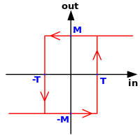
This dual threshold action is called hysteresis and implies that the Schmitt trigger possesses memory and can act as a bistable multivibrator (latch or flip-flop).
They are also used in closed loop negative feedback configurations to implement relaxation oscillators, used in function generators and switching power supplies.
Any active circuit can be made to behave as a Schmitt trigger by applying positive feedback so that the loop gain is more than one.
These circuits contain an attenuator (the B box in the figure on the right) and an adder (the circle with "+" inside) in addition to an amplifier acting as a comparator.
Two different unidirectional thresholds are assigned in this case to two separate open-loop comparators (without hysteresis) driving a bistable multivibrator (latch) or flip-flop.
The comparator output drives the second common collector stage Q2 (an emitter follower) through the voltage divider R1-R2.
This configuration can be considered as a differential amplifier with series positive feedback between its non-inverting input (Q2 base) and output (Q1 collector) that forces the transition process.
To make the positive feedback dominate over the negative one and to obtain a hysteresis, the proportion between the two collector resistors is chosen so that RC1 > RC2.
The Q2 base voltage is determined by the divider described above so that Q2 is conducting and the trigger output is in the low state.
Neglecting VBE, the high threshold value is approximately The output voltage is low but well above ground.
It is approximately equal to the high threshold and may not be low enough to be a logical zero for subsequent digital circuits.
With the trigger now in the high state, if the input voltage drops enough (below the low threshold), Q1 begins cutting off.
The voltage across RE rises, further reducing the Q1 base-emitter potential in the same avalanche-like manner, and Q1 ceases to conduct.
To simplify the circuit, the R1–R2 voltage divider can be omitted connecting Q1 collector directly to Q2 base.
This parallel positive feedback creates the needed hysteresis that is controlled by the proportion between the resistances of R1 and R2.
For instance, if the Schmitt trigger is currently in the high state, the output will be at the positive power supply rail (+VS).
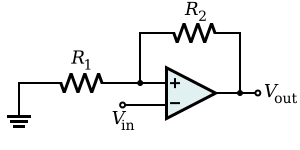
The output voltage V+ of the resistive summer can be found by applying the superposition theorem: The comparator will switch when V+=0.
If R1 is zero or R2 is infinity (i.e., an open circuit), the band collapses to zero width, and it behaves as a standard comparator.
A unique property of circuits with parallel positive feedback is the impact on the input source.
Here there is no virtual ground, and the steady op-amp output voltage is applied through R1-R2 network to the input source.
However, if the input voltage is within the hysteresis cycle (between the high and low thresholds), the circuit can be inverting as well as non-inverting.
The output voltage is undefined and it depends on the last state so the circuit behaves like an elementary latch.
If the Schmitt trigger is currently in the high state, the output will be at the positive power supply rail (+VS).
If R1 is zero (i.e., a short circuit) or R2 is infinity, the band collapses to zero width, and it behaves as a standard comparator.
One application of a Schmitt trigger is to increase the noise immunity in a circuit with only a single input threshold.
The net effect is that the output of the Schmitt trigger only passes from low to high after a received infrared signal excites the photodiode for longer than some known period, and once the Schmitt trigger is high, it only moves low after the infrared signal ceases to excite the photodiode for longer than a similar known period.
This is achieved by connecting a single RC integrating circuit between the output and the input of an inverting Schmitt trigger.
The output will be a continuous square wave whose frequency depends on the values of R and C, and the threshold points of the Schmitt trigger.
Since multiple Schmitt trigger circuits can be provided by a single integrated circuit (e.g. the 4000 series CMOS device type 40106 contains 6 of them), a spare section of the IC can be quickly pressed into service as a simple and reliable oscillator with only two external components.
The result, which is shown on the right, is that the output automatically oscillates from VSS to VDD as the capacitor charges from one Schmitt trigger threshold to the other.


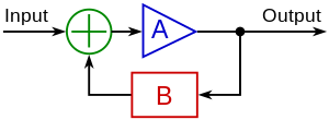
A > 1 is the amplifier gain
B < 1 is the feedback transfer function