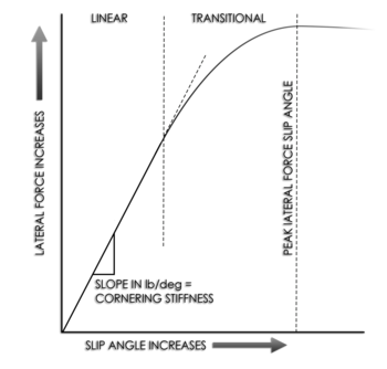
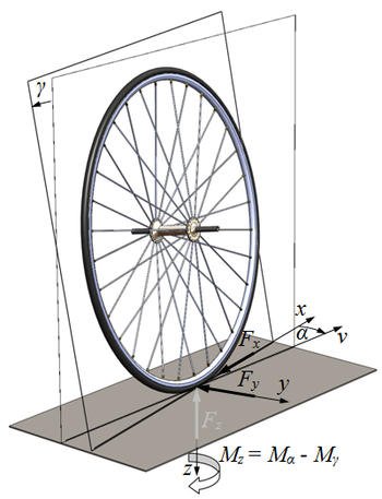
Slip angle
A non-zero slip angle arises because of deformation in the tire carcass and tread.
While it is equally valid to frame this as the tire/wheel being deflected away from the stationary tread element, convention is for the co-ordinate system to be fixed around the wheel mid-plane.
While the tread element moves through the contact patch it is deflected further from the wheel mid-plane.
[2] Actual instantaneous slip angles depend on many factors, including the condition of the road surface, but a vehicle's suspension can be designed to promote specific dynamic characteristics.
A principal means of adjusting developed slip angles is to alter the relative roll couple (the rate at which weight transfers from the inside to the outside wheel in a turn) front to rear by varying the relative amount of front and rear lateral load transfer.
Because of asymmetries in the side-slip along the length of the contact patch, the resultant force of this side-slip occurs away from the geometric center of the contact patch, a distance described as the pneumatic trail, and so creates a torque on the tire, the so-called self aligning torque.
There are two main ways to measure slip angle of a tire: on a vehicle as it moves, or on a dedicated testing device.
Various test machines have been developed to measure slip angle in a controlled environment.
That uses a 3-meter diameter disk that rotates under a tire held at a fixed steer and camber angle, up to 54 degrees.
Sensors measure the force and moment generated, and a correction is made to account for the curvature of the track.