Solid modeling
Simulation, planning, and verification of processes such as machining and assembly were one of the main catalysts for the development of solid modeling.
Beyond traditional manufacturing, solid modeling techniques serve as the foundation for rapid prototyping, digital data archival and reverse engineering by reconstructing solids from sampled points on physical objects, mechanical analysis using finite elements, motion planning and NC path verification, kinematic and dynamic analysis of mechanisms, and so on.
A central problem in all these applications is the ability to effectively represent and manipulate three-dimensional geometry in a fashion that is consistent with the physical behavior of real artifacts.
Solid modeling research and development has effectively addressed many of these issues, and continues to be a central focus of computer-aided engineering.
[2] All manufactured components have finite size and well behaved boundaries, so initially the focus was on mathematically modeling rigid parts made of homogeneous isotropic material that could be added or removed.
Assuming ℝ3 is endowed with the typical Euclidean metric, a neighborhood of a point p ∈X takes the form of an open ball.
A triangulation of a semi-analytic set into a collection of points, line segments, triangular faces, and tetrahedral elements is an example of a stratification that is commonly used.
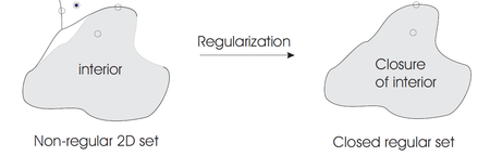
The key property that facilitates this consistency is that the class of closed regular subsets of ℝn coincides precisely with homogeneously n-dimensional topological polyhedra.
Based on assumed mathematical properties, any scheme of representing solids is a method for capturing information about the class of semi-analytic subsets of Euclidean space.
For example, solids defined via combinations of regularized Boolean operations cannot necessarily be represented as the sweep of a primitive moving according to a space trajectory, except in very simple cases.
The other main drawback of this scheme is the difficulty of writing algorithms for computing properties of represented solids.
A considerable amount of family-specific information must be built into the algorithms and therefore each generic primitive must be treated as a special case, allowing no uniform overall treatment.
They can, however, represent coarse approximations of parts and can be used to improve the performance of geometric algorithms, especially when used in conjunction with other representations such as constructive solid geometry.
Cell decompositions in the form of triangulations are the representations used in 3D finite elements for the numerical solution of partial differential equations.
CSG representations take the form of ordered binary trees where non-terminal nodes represent either rigid transformations (orientation preserving isometries) or regularized set operations.
CSG representations are particularly useful for capturing design intent in the form of features corresponding to material addition or removal (bosses, holes, pockets etc.).
The relatively simple data structure and elegant recursive algorithms[7] have further contributed to the popularity of CSG.
However, current research has shown several approximations of three dimensional shapes moving across one parameter, and even multi-parameter motions.
The simplest form of a predicate is the condition on the sign of a real valued function resulting in the familiar representation of sets by equalities and inequalities.
Furthermore, the theory of R-functions allow conversions of such representations into a single function inequality for any closed semi analytic set.
Features are defined to be parametric shapes associated with attributes such as intrinsic geometric parameters (length, width, depth etc.
Features are generally expected to form a basis for linking CAD with downstream manufacturing applications, and also for organizing databases for design data reuse.
Parametric feature based modeling is frequently combined with constructive binary solid geometry (CSG) to fully describe systems of complex objects in engineering.
Solid modeling software creates a virtual 3D representation of components for machine design and analysis.
[11] A typical graphical user interface includes programmable macros, keyboard shortcuts and dynamic model manipulation.
The ability to dynamically re-orient the model, in real-time shaded 3-D, is emphasized and helps the designer maintain a mental 3-D image.
Engineering solid models are built mostly with sketcher-based features; 2-D sketches that are swept along a path to become 3-D.
Optical 3D scanners can be used to create point clouds or polygon mesh models of external body features.
Because CAD programs running on computers "understand" the true geometry comprising complex shapes, many attributes of/for a 3‑D solid, such as its center of gravity, volume, and mass, can be quickly calculated.
Despite its many radii and the shallow pyramid on each of its six faces, its properties are readily calculated for the designer, as shown in the screenshot at right.