Technical drawing
To make the drawings easier to understand, people use familiar symbols, perspectives, units of measurement, notation systems, visual styles, and page layout.
Together, such conventions constitute a visual language and help to ensure that the drawing is unambiguous and relatively easy to understand.
Many of the symbols and principles of technical drawing are codified in an international standard called ISO 128.
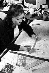
[2] The basic drafting procedure is to place a piece of paper (or other material) on a smooth surface with right-angle corners and straight sides—typically a drawing board.
This basic drafting system requires an accurate table and constant attention to the positioning of the tools.
A common error is to allow the triangles to push the top of the T-square down slightly, thereby throwing off all angles.
Even tasks as simple as drawing two angled lines meeting at a point require a number of moves of the T-square and triangles, and in general, drafting can be a time-consuming process.
A solution to these problems was the introduction of the mechanical "drafting machine", an application of the pantograph (sometimes referred to incorrectly as a "pentagraph" in these situations) which allowed the drafter to have an accurate right angle at any point on the page quickly.
In addition to the mastery of the mechanics of drawing lines, arcs and circles (and text) onto a piece of paper—with respect to the detailing of physical objects—the drafting effort requires a thorough understanding of geometry, trigonometry and spatial comprehension, and in all cases demands precision and accuracy, and attention to detail of high order.
Today, the mechanics of the drafting task have largely been automated and accelerated through the use of computer-aided design systems (CAD).
2D CAD systems can be used to create plans for large projects such as buildings and aircraft but provide no way to check the various components will fit together.
The main scope for error comes in setting the parameter of first or third angle projection and displaying the relevant symbol on the technical drawing.
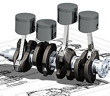
Buildings, aircraft, ships, and cars are modelled, assembled, and checked in 3D before technical drawings are released for manufacture.
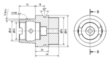
The only standard across engineering workshop drawings is in the creation of orthographic projections and cross-section views.
Engineering drawings are usually created in accordance with standardized conventions for layout, nomenclature, interpretation, appearance (such as typefaces and line styles), size, etc.
The end goal of an engineering drawing is to convey all the required information that will allow a manufacturer to produce that component.
[7] Practitioners reported that diagramming helped with analysing requirements,[7]: 539 design, refactoring, documentation, onboarding, communication with stake holders.
The aim of technical illustration is "to generate expressive images that effectively convey certain information via the visual channel to the human observer".
[9] The main purpose of technical illustration is to describe or explain these items to a more or less nontechnical audience.
The visual image should be accurate in terms of dimensions and proportions, and should provide "an overall impression of what an object is or does, to enhance the viewer's interest and understanding".
Cross hatching, stippling, and other low abstraction techniques gave greater depth and dimension to the subject matter".
Therefore, any surface that is not in line with the three major axis needs its own projection plane to show the features correctly.
[13] It shows the components of an object slightly separated by distance or suspended in surrounding space in the case of a three-dimensional exploded diagram.
An exploded view drawing (EVD) can show the intended assembly of mechanical or other parts.
[13] The drawing must show every feature of the invention specified in the claims and is required by the patent office rules to be in a particular form.
These are based upon the working drawings and updated to reflect any changes or alterations undertaken during construction or manufacture.