Engineering drawing
Although mostly consisting of pictographic representations, abbreviations and symbols are used for brevity and additional textual explanations may also be provided to convey the necessary information.
As a necessary means for visually conveying ideas, technical drawing has been in one form or another a part of human history since antiquity.
The use of these early drawings was to express architectural and engineering concepts for large cultural structures: the temples, monuments, and public infrastructure.
Basic forms of technical drawing were used by the Egyptians and Mesopotamians to create highly detailed irrigation systems, pyramids, and other such sophisticated structures.
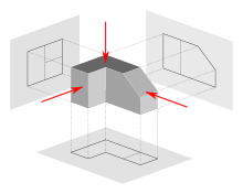
During the same period, the French mathematician Gaspard Monge developed descriptive geometry, a means of representing three-dimensional objects in two-dimensional space, and contributed to technical drawing in a major way.
L. T. C. Rolt's biography of Isambard Kingdom Brunel, to whom Marc contributed in 1799 with his detailed drawings of block-making machinery, testified to the developing nature of British engineering methods.
By applying what we now call mechanical drawing techniques to depict three-dimensional machinery on a two-dimensional plane more efficient manufacturing processes as well as greater precision were enabled.
These innovations were essential as the world began to move toward mechanized production, and complex engineering projects, such as bridges, railways, and ships, required highly detailed and accurate technical representations to succeed.
New conventions and symbols were created by engineers; the use of which became standardized throughout industries, so that any person who could read a technical drawing could know the specifications of a component or structure.
These tools helped drafters achieve the high degree of precision necessary for increasingly complex projects, such as skyscrapers, airplanes, and automobiles.
This digital transformation has not only increased efficiency but also broadened the possibilities for innovation, enabling engineers to tackle challenges that were previously unimaginable.
The evolution of technical drawing is a testament to human ingenuity, demonstrating how the ability to convey complex ideas visually has been pivotal in the advancement of civilization.
These apply widely in the United States, although ISO 8015 (Geometrical product specifications (GPS) — Fundamentals — Concepts, principles and rules) is now also important.
Some of the tools of manual drafting include pencils, pens and their ink, straightedges, T-squares, French curves, triangles, rulers, protractors, dividers, compasses, scales, erasers, and tacks or push pins.
(Slide rules used to number among the supplies, too, but nowadays even manual drafting, when it occurs, benefits from a pocket calculator or its onscreen equivalent.)
Producing drawings usually involves creating an original that is then reproduced, generating multiple copies to be distributed to the shop floor, vendors, company archives, and so on.
The classic reproduction methods involved blue and white appearances (whether white-on-blue or blue-on-white), which is why engineering drawings were long called, and even today are still often called, "blueprints" or "bluelines", even though those terms are anachronistic from a literal perspective, since most copies of engineering drawings today are made by more modern methods (often inkjet or laser printing) that yield black or multicolour lines on white paper.
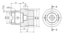
Almost all engineering drawings (except perhaps reference-only views or initial sketches) communicate not only geometry (shape and location) but also dimensions and tolerances[1] for those characteristics.
The simplest dimensioning system just specifies distances between points (such as an object's length or width, or hole center locations).
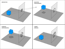
[7] As shown above, the determination of what surface constitutes the front, back, top, and bottom varies depending on the projection method used.
The true size and shape of any feature in an engineering drawing can only be known when the Line of Sight (LOS) is perpendicular to the plane being referenced.
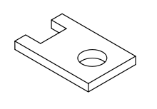
Thus, great effort is put into having an engineering drawing accurately depict size, shape, form, aspect ratios between features, and so on.
(For example, a sketch of a hole that is clearly not round still accurately defines the part as having a true round hole, as long as the label says "10mm DIA", because the "DIA" implicitly but objectively tells the user that the skewed drawn circle is a symbol representing a perfect circle.)
But if a mathematical model—essentially, a vector graphic—is declared to be the official definition of the part, then any amount of "scaling the drawing" can make sense; there may still be an error in the model, in the sense that what was intended is not depicted (modeled); but there can be no error of the "not to scale" type—because the mathematical vectors and curves are replicas, not symbols, of the part features.
Even in dealing with 2D drawings, the manufacturing world has changed since the days when people paid attention to the scale ratio claimed on the print, or counted on its accuracy.
A radially-aligned line with arrowhead pointing to the circular feature, called a leader, is used in conjunction with both diametral and radial dimensions.
The ISO character set (font) has a seriffed one, a barred seven, an open four, six, and nine, and a round topped three, that improves legibility when, for example, an A0 drawing has been reduced to A1 or even A3 (and perhaps enlarged back or reproduced/faxed/ microfilmed &c).
It standardizes eight mandatory data fields:[16] Traditional locations for the title block are the bottom right (most commonly) or the top right or center.
Thus, if the resulting product is wrong, the worker or manufacturer are protected from liability as long as they have faithfully executed the instructions conveyed by the drawing.
Because manufacturing and construction are typically very expensive processes (involving large amounts of capital and payroll), the question of liability for errors has legal implications.