Stepper motor
The stepper motor is known for its property of converting a train of input pulses (typically square waves) into a precisely defined increment in the shaft’s rotational position.
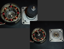
Stepper motors effectively have multiple "toothed" electromagnets arranged as a stator around a central rotor, a gear-shaped piece of iron.
To make the motor shaft turn, one electromagnet is first given power, which magnetically attracts the gear's teeth.
There are three main types of stepper motors: permanent magnet, variable reluctance, and hybrid synchronous.
If current is removed, a lesser detent still remains, holding shaft position against spring or other torque influences.
Permanent magnet stepper motors have simple DC switching electronics, a power-off detent, and no position readout.
Such applications track position simply by counting the number of steps that each motor has been instructed to take.
Hybrid synchronous motors are a combination of the permanent magnet and variable reluctance types, to maximize power in a small size.
There are two basic winding arrangements for the electromagnetic coils in a two phase stepper motor: bipolar and unipolar.
A quick way to determine if the stepper motor is working is to short circuit every two pairs and try turning the shaft.
[6] Dithering the stepper signal at a higher frequency than the motor can respond to will reduce this "static friction" effect.
A unipolar motor has twice the amount of wire in the same space, but only half used at any point in time, hence is 50% efficient (or approximately 70% of the torque output available).
Though a bipolar stepper motor is more complicated to drive, the abundance of driver chips means this is much less difficult to achieve.
[7] While they are more expensive, they do have a higher power density and with the appropriate drive electronics are often better suited to the application[citation needed].
Torque curves may be extended to greater speeds if the stator poles can be reversed more quickly, the limiting factor being a combination of the winding inductance.
As the motor's rotor turns, a sinusoidal voltage is generated proportional to the speed (step rate).
Modern voltage-mode drivers overcome some of these limitations by approximating a sinusoidal voltage waveform to the motor phases.
The winding inductance smooths the current which reaches a level according to the square wave duty cycle.
This current level is monitored by the controller by measuring the voltage across a small sense resistor in series with the winding.
A full-step waveform is a gross approximation of a sinusoid, and is the reason why the motor exhibits so much vibration.
In animated figure shown above, if we change it to half-stepping, then it will take 8 steps to rotate by 1 tooth position.
Resolution will be limited by the mechanical stiction, backlash, and other sources of error between the motor and the end device.
Additionally, soft magnetic material with many teeth on the rotor and stator cheaply multiplies the number of poles (reluctance motor).
As speeds further increase, the current will not reach the rated value, and eventually the motor will cease to produce torque.
At low speeds the stepper motor can synchronize itself with an applied step frequency, and this pull-in torque must overcome friction and inertia.
This measurement is taken across a wide range of speeds and the results are used to generate the stepper motor's dynamic performance curve.
These figures can be helpful for more in-depth electronics design, when deviating from standard supply voltages, adapting third party driver electronics, or gaining insight when choosing between motor models with otherwise similar size, voltage, and torque specifications.
They are typically digitally controlled as part of an open loop system for use in holding or positioning applications.
Commercially, stepper motors are used in floppy disk drives, flatbed scanners, computer printers, plotters, slot machines, image scanners, compact disc drives, intelligent lighting, camera lenses, CNC machines, and 3D printers.
[12][13] A stepper motor system consists of three basic elements, often combined with some type of user interface (host computer, PLC or dumb terminal):
Frame 2: The top electromagnet (1) is turned off, and the right electromagnet (2) is energized, pulling the teeth into alignment with it. This results in a rotation of 3.6° in this example.
Frame 3: The bottom electromagnet (3) is energized; another 3.6° rotation occurs.
Frame 4: The left electromagnet (4) is energized, rotating again by 3.6°. When the top electromagnet (1) is again enabled, the rotor will have rotated by one tooth position; since there are 25 teeth, it will take 100 steps to make a full rotation in this example.