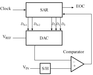
Successive-approximation ADC
The resulting code is the digital approximated output of the sampled input voltage.
To show this mathematically, the normalized input voltage is represented as x in [−1, 1] by letting Vin = xVref.
It follows using mathematical induction that the approximation of the nth iteration theoretically has a bounded accuracy of: |xn − x| ≤ 1/2n.
When implemented as a real analog circuit, circuit inaccuracies and noise may cause the binary search algorithm to incorrectly remove values it believes Vin cannot be, so a successive-approximation ADC might not output the closest value.
As of 2001[update], the component-matching limitations of the DAC generally limited the linearity to about 12 bits in practical designs and mandated some form of trimming or calibration to achieve the necessary linearity for more than 12 bits.
[2] SAR ADCs are commonly found on microcontrollers because they are easy to integrate into a mixed-signal process, but suffer from inaccuracies from the internal reference voltage resistor ladder and clock and signal noise from the rest of the microcontroller, so external ADC chips may provide better accuracy.
[3] Example 1: The steps to converting an analog input to 9-bit digital, using successive-approximation, are shown here for all voltages from 5 V to 0 V in 0.1 V iterations.
Then by adding the next weight to the previous result, comparing again, and repeating until all the bits and their weights have been compared to the input, the result, a binary number representing the analog input, is found.
If the input voltage is higher, then on the next clock cycle, the register changes its value to that illustrated in the figure by following the red line.
The simplified structure of this type of ADC that acts on 2n volts range can be expressed as an algorithm: The successive-approximation ADC can be alternatively explained by first uniformly assigning each digital output to corresponding ranges as shown.