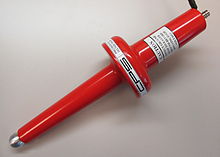
Test probe
To achieve high accuracy, the test instrument and its probe must not significantly affect the voltage being measured.
This is accomplished by ensuring that the combination of instrument and probe exhibit a sufficiently high impedance that will not load the DUT.
Within the probe body, the wire is connected to a rigid, pointed metal tip that contacts the DUT.
Because of the high frequencies often involved, oscilloscopes do not normally use simple wires ("flying leads") to connect to the DUT.
Consequently, a one-meter high-impedance direct (1×) coaxial probe may load the circuit with a capacitance of about 110 pF and a resistance of 1 megohm.
Oscilloscope probes are characterised by their frequency limit, where the amplitude response has fallen by 3 dB, and/or by their rise time
A typical probe uses a 9 megohm series resistor shunted by a low-value capacitor to make an RC compensated divider with the cable capacitance and scope input.
In practice, there will be an adjustment so the operator can precisely match the low frequency time constant (called compensating the probe).
In that time frame, the cable looks like its characteristic impedance, and there will be reflections from the transmission line mismatch at the scope input and the probe that causes ringing.
A DC attenuator with resistive divider is supplemented with capacitors, so that the frequency response is predictable over the range of interest.
The signal is then transmitted from the probe head to the oscilloscope over a special lossy coaxial cable that is designed to minimize capacitance and ringing.
A high frequency oscilloscope presents a matched load (usually 50 ohms) at its input, which minimizes reflections at the scope.
Probing with a matching 50-ohm transmission line would offer high frequency performance, but it would unduly load most circuits.
Active probes are commonly seen by the circuit under test as a capacitance of 1 picofarad or less in parallel with 1 megohm resistance.
Because of their inherent low voltage rating, there is little need to provide high-voltage insulation for operator safety.
This allows the heads of active probes to be extremely small, making them very convenient for use with modern high-density electronic circuits.
[15] At extreme high frequencies a modern digital scope requires that the user solder a preamp to the DUT to get 50GS/s, 20 GHz performance.
To maximize the common-mode rejection ratio (CMRR), differential probes must provide two signal paths that are as nearly identical as possible, matched in overall attenuation, frequency response, and time delay.
In the past, this was done by designing passive probes with two signal paths, requiring a differential amplifier stage at or near the oscilloscope.
With advances in solid-state electronics, it has become practical to put the differential amplifier directly within the probe head, greatly easing the requirements on the rest of the signal path (since it now becomes single-ended rather than differential and the need to match parameters on the signal path is removed).
A modern differential probe usually has two metal extensions which can be adjusted by the operator to simultaneously touch the appropriate two points on the DUT.
Tips that have a small plastic insulating foot with indentations into it can make it easier to probe very-fine-pitch integrated circuits; the indentations mate with the pitch of the IC leads, stabilizing the probe against the shaking of the user's hand and thereby help to maintain contact on the desired pin.
The oscilloscope can then adjust its user displays to automatically take into account the attenuation and other factors caused by the probe.
On the other hand, active probes are almost always vendor-specific due to their power requirements, offset voltage controls, etc.
Probes intended for up to 100 kV typically employ a resistor voltage divider, with an input resistance of hundreds or thousands of megohms to minimize circuit loading.
High linearity and accuracy is achieved by using resistors with extremely low voltage coefficients, in matched sets that maintain a consistent, precise divider ratio across the probe's operating temperature.
To mitigate these effects, voltage divider probes usually include additional components that improve frequency response and allow them to be calibrated for different meter loads.
The sampling resistance needs to be small enough not to affect circuit operation significantly, but large enough to provide a good reading.
High-frequency, small-signal, passive current probes typically have a frequency range of several kilohertz to over 100 MHz.
Most current probes are self-contained, drawing power from a battery or the instrument, but a few require the use of an external amplifier unit.