Voltmeter
Analog voltmeters move a pointer across a scale in proportion to the voltage measured and can be built from a galvanometer and series resistor.
Any measurement that can be converted to a voltage can be displayed on a meter that is suitably calibrated; for example, pressure, temperature, flow or level in a chemical process plant.
This is achieved by using a sensitive galvanometer in series with a high resistance, and then the entire instrument is connected in parallel with the circuit examined.
Measurement of AC voltage requires a rectifier in the circuit so that the coil deflects in only one direction.
Some moving-coil instruments are also made with the zero position in the middle of the scale instead of at one end; these are useful if the voltage reverses its polarity.
Voltmeters operating on the electrostatic principle use the mutual repulsion between two charged plates to deflect a pointer attached to a spring.
Today these circuits use a solid-state amplifier using field-effect transistors, hence FET-VM, and appear in handheld digital multimeters as well as in bench and laboratory instruments.
To ensure that a DVM's accuracy is within the manufacturer's specified tolerances, it must be periodically calibrated against a voltage standard such as the Weston cell.
The first digital voltmeter was invented and produced by Andrew Kay of Non-Linear Systems (and later founder of Kaypro) in 1954.
[1] Simple AC voltmeters use a rectifier connected to a DC measurement circuit, which responds to the average value of the waveform.
If the waveform departs significantly from the sinewave assumed in the calibration, the meter will be inaccurate, though for simple wave shapes the reading can be corrected by multiplying by a constant factor.

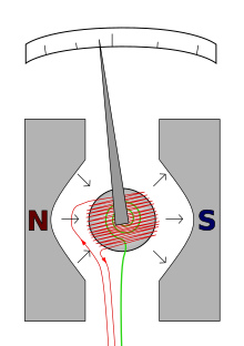
- The red wire carries the current to be measured.
- The restoring spring is shown in green.
- N and S are the north and south poles of the magnet.
