Wien bridge oscillator
The oscillator is based on a bridge circuit originally developed by Max Wien in 1891 for the measurement of impedances.
The circuit shown to the right depicts a once-common implementation of the oscillator, with automatic gain control using an incandescent lamp.
The oscillations would build until the vacuum tube's grid would start conducting current, which would increase losses and limit the output amplitude.
"[7] In 1937, Larned Meacham described using a filament lamp for automatic gain control in bridge oscillators.
[18] Hewlett's June 1939 engineer's degree thesis used a lamp to control the amplitude of a Wien bridge oscillator.
[19] Hewlett's oscillator produced a sinusoidal output with a stable amplitude and low distortion.
It can produce total harmonic distortion in the range of 1-5%, depending on how carefully it is trimmed.
Consequently, for low distortion, the oscillator's output amplitude should be a small fraction of the amplifier's dynamic range.
[9] Instead of using tube overloading to control the amplitude, Meacham proposed a circuit that set the loop gain to unity while the amplifier is in its linear region.
Meacham's circuit included a quartz crystal oscillator and a lamp in a Wheatstone bridge.
At frequencies above resonance, the crystal is inductive and the gain of the negative feedback branch has a positive phase shift.
In 1944 (after Hewlett's design), J. K. Clapp modified Meacham's circuit to use a vacuum tube phase inverter instead of a transformer to drive the bridge.
[23][24] A modified Meacham oscillator uses Clapp's phase inverter but substitutes a diode limiter for the tungsten lamp.
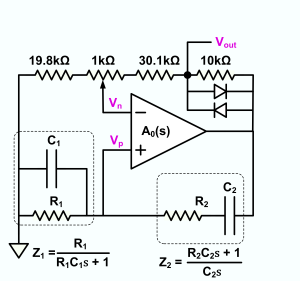
[25] William R. Hewlett's Wien bridge oscillator can be considered as a combination of a differential amplifier and a Wien bridge, connected in a positive feedback loop between the amplifier output and differential inputs.
To simplify analysis, all the components other than R1, R2, C1 and C2 can be modeled as a non-inverting amplifier with a gain of 1+Rf/Rb and with a high input impedance.
R1, R2, C1 and C2 form a bandpass filter which is connected to provide positive feedback at the frequency of oscillation.
This does not change the principles of the circuit's operation, but it does reduce the amplitude of the output at equilibrium because the bias current provides part of the heating of the lamp.
[28] Wien's bridge is used for precision measurement of capacitance in terms of resistance and frequency.
Schilling further says that the condition of oscillation is T=1 which, is satisfied by and Another analysis, with particular reference to frequency stability and selectivity, is in Strauss (1970, p. 671) and Hamilton (2003, p. 449).
[31] The amplitude of electronic oscillators tends to increase until clipping or other gain limitation is reached.
The result is a negative feedback system that stabilizes the output amplitude to a constant value.
With this form of amplitude control, the oscillator operates as a near ideal linear system and provides a very low distortion output signal.
At low frequencies, as the time period of the Wien bridge oscillator approaches the thermal time constant of the incandescent bulb, the circuit operation becomes more nonlinear, and the output distortion rises significantly.
Light bulbs have their disadvantages when used as gain control elements in Wien bridge oscillators, most notably a very high sensitivity to vibration due to the bulb's microphonic nature amplitude modulating the oscillator output, a limitation in high frequency response due to the inductive nature of the coiled filament, and current requirements that exceed the capability of many op-amps.
Modern Wien bridge oscillators have used other nonlinear elements, such as diodes, thermistors, field effect transistors, or photocells for amplitude stabilization in place of light bulbs.
[33] Small perturbations in the value of Rb cause the dominant poles to move back and forth across the jω (imaginary) axis.
If the perturbation is very small, the magnitude of the equivalent Q is very large so that the amplitude changes slowly.
The light bulb has thermal inertia so that its power to resistance transfer function exhibits a single pole low pass filter.
This would cause poor transient response in the control loop due to low phase margin.
Bernard M. Oliver[35] showed that slight compression of the gain by the amplifier mitigates the envelope transfer function so that most oscillators show good transient response, except in the rare case where non-linearity in the vacuum tubes canceled each other producing an unusually linear amplifier.