Electrical discharge machining
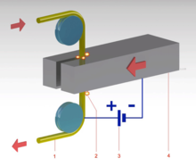
[1] Material is removed from the work piece by a series of rapidly recurring current discharges between two electrodes, separated by a dielectric liquid and subject to an electric voltage.
[3][4][5][6] Simultaneously but independently, an American team, Harold Stark, Victor Harding, and Jack Beaver, developed an EDM machine for removing broken drills and taps from aluminium castings.
Later machines based on their design used vacuum tube circuits that produced thousands of sparks per second, significantly increasing the speed of cutting.
[14] EDM is often included in the "non-traditional" or "non-conventional" group of machining methods together with processes such as electrochemical machining (ECM), water jet cutting (WJ, AWJ), laser cutting, and opposite to the "conventional" group (turning, milling, grinding, drilling, and any other process whose material removal mechanism is essentially based on mechanical forces).
The flushing action can be inadequate to restore the insulating properties of the dielectric so that the current always happens in the point of the inter-electrode volume (this is referred to as arcing), with a consequent unwanted change of shape (damage) of the tool-electrode and workpiece.
Ultimately, a description of this process in a suitable way for the specific purpose at hand is what makes the EDM area such a rich field for further investigation and research.
In this way, a large number of current discharges (colloquially also called sparks) happen, each contributing to the removal of material from both tool and workpiece, where small craters are formed.
If the final geometry is obtained using a usually simple-shaped electrode which is moved along several directions and is possibly also subject to rotations, often the term EDM milling is used.
[18] In any case, the severity of the wear is strictly dependent on the technological parameters used in the operation (for instance: polarity, maximum current, open circuit voltage).
[22] Van Dijck presented a thermal model together with a computational simulation to explain the phenomena between the electrodes during electric discharge machining.
However, as Van Dijck himself admitted in his study, the number of assumptions made to overcome the lack of experimental data at that time was quite significant.
Further models of what occurs during electric discharge machining in terms of heat transfer were developed in the late eighties and early nineties.
These models give the most authoritative support for the claim that EDM is a thermal process, removing material from the two electrodes because of melting or vaporization, along with pressure dynamics established in the spark-gap by the collapsing of the plasma channel.
This would be possible because the material on the surface has altered mechanical properties due to an increased temperature caused by the passage of electric current.
The authors' simulations showed how they might explain EDM better than a thermal model (melting or evaporation), especially for small discharge energies, which are typically used in μ-EDM and in finishing operations.
As the electrode approaches the workpiece, dielectric breakdown occurs in the fluid, forming a plasma channel,[16][23][24][25] and a small spark jumps.
As the base metal is eroded, and the spark gap subsequently increased, the electrode is lowered automatically by the machine so that the process can continue uninterrupted.
Several hundred thousand sparks occur per second, with the actual duty cycle carefully controlled by the setup parameters.
Although not directly affecting the machining of the part, the off time allows the flushing of dielectric fluid through a nozzle to clean out the eroded debris.
[28] Wire-cut EDM is typically used to cut plates as thick as 300 mm (12 in) and to make punches, tools, and dies from hard metals that are difficult to machine with other methods.
The wire, which is constantly fed from a spool, is held between upper and lower diamond guides which is centered in a water nozzle head.
On most machines, the upper guide can also move independently in the z–u–v axis, giving rise to the ability to cut tapered and transitioning shapes (circle on the bottom, square at the top for example).
Along with tighter tolerances, multi axis EDM wire-cutting machining centers have added features such as multi heads for cutting two parts at the same time, controls for preventing wire breakage, automatic self-threading features in case of wire breakage, and programmable machining strategies to optimize the operation.
Wire-cutting EDM is commonly used when low residual stresses are desired, because it does not require high cutting forces for removal of material.
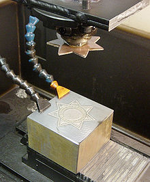
The resultant negative die is then hardened and used in a drop hammer to produce stamped flats from cutout sheet blanks of bronze, silver, or low proof gold alloy.
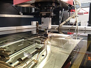
A separate EDM head specifically for small hole drilling is mounted on a wire-cut machine and allows large hardened plates to have finished parts eroded from them as needed and without pre-drilling.
The high-temperature, very hard, single crystal alloys employed in these blades makes conventional machining of these holes with high aspect ratio extremely difficult, if not impossible.
Small hole EDM is also used to create microscopic orifices for fuel system components, spinnerets for synthetic fibers such as rayon, and other applications.
Several manufacturers produce EDM machines for the specific purpose of removing broken cutting tools and fasteners from work pieces.
The metal disintegration process removes only the center of the broken tool or fastener, leaving the hole intact and allowing a ruined part to be reclaimed.