Yagi–Uda antenna
[2][3][4] It was invented in 1926 by Shintaro Uda of Tohoku Imperial University, Japan,[5] with a lesser role played by his boss Hidetsugu Yagi.
They receive and reradiate the radio waves from the driven element but in a different phase determined by their exact lengths.
[3][4] It has moderate to high gain of up to 20 dBi,[3] depending on the number of elements used, and a front-to-back ratio of up to 20 dB.
[2] The antenna was invented by Shintaro Uda of Tohoku Imperial University, Japan,[5] in 1926, with a lesser role played by Hidetsugu Yagi.
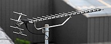
The Yagi–Uda antenna typically consists of a number of parallel thin rod elements, each approximately a half wave in length.
[4] The most common form of the driven element is one fed at its centre so its two halves must be insulated where the boom supports them.
[4] For applications that require wider bandwidths, such as terrestrial television, Yagi–Uda antennas commonly feature trigonal reflectors, and larger diameter conductors, in order to cover the relevant portions of the VHF and UHF bands.
These elaborate designs create electrical breaks along each element (both sides) at which point a parallel LC (inductor and capacitor) circuit is inserted.
This so-called trap has the effect of truncating the element at the higher frequency band, making it approximately a half wavelength in length.
At the lower frequency, the entire element (including the remaining inductance due to the trap) is close to half-wave resonance, implementing a different Yagi–Uda antenna.
It is proportional to the effective length of the antenna and is in phase with the incident electric field if the passive dipole is excited exactly at its resonance frequency.
As is well known in transmission line theory, a short circuit reflects the incident voltage 180 degrees out of phase.
The net effect is a wave emitted by the director (blue) which is about 70° (20° - 90°) retarded with respect to that from the driven element (green), in this particular design.
The combination of the director's position and shorter length has thus obtained a unidirectional rather than the bidirectional response of the driven (half-wave dipole) element alone.
And now knowing the phase (and amplitude) of I2 in relation to I1 as computed above allows us to determine the radiation pattern (gain as a function of direction) due to the currents flowing in these two elements.
The current distribution along a real antenna element is only approximately given by the usual assumption of a classical standing wave, requiring a solution of Hallen's integral equation taking into account the other conductors.
Such a complete exact analysis, considering all of the interactions mentioned, is rather overwhelming, and approximations are inevitable on the path to finding a usable antenna.
A well-known reference employed in the latter approach is a report published by the United States National Bureau of Standards (NBS) (now the National Institute of Standards and Technology (NIST)) that provides six basic designs derived from measurements conducted at 400 MHz and procedures for adapting these designs to other frequencies.
Yagi demonstrated a proof of concept, but the engineering problems proved to be more onerous than conventional systems.
[18] Yagi published the first English-language reference on the antenna in a 1928 survey article on short wave research in Japan and it came to be associated with his name.
The Yagi was first widely used during World War II for airborne radar sets, because of its simplicity and directionality.
[18][19] Despite its being invented in Japan, many Japanese radar engineers were unaware of the design until late in the war, partly due to rivalry between the Army and Navy.
The Japanese military authorities first became aware of this technology after the Battle of Singapore when they captured the notes of a British radar technician that mentioned "yagi antenna".
Two types that often carried such equipment are the Grumman TBF Avenger carrier-based US Navy aircraft and the Consolidated PBY Catalina long range patrol seaplane.
Vertically polarized arrays can be seen on the cheeks of the P-61 and on the nose cones of many WWII aircraft, notably the Lichtenstein radar-equipped examples of the German Junkers Ju 88R-1 fighter-bomber, and the British Bristol Beaufighter night-fighter and Short Sunderland flying-boat.
Indeed, the latter had so many antenna elements arranged on its back – in addition to its formidable turreted defensive armament in the nose and tail, and atop the hull – it was nicknamed the fliegendes Stachelschwein, or "Flying Porcupine" by German airmen.
[22] The experimental Morgenstern German AI VHF-band radar antenna of 1943–44 used a "double-Yagi" structure from its 90° angled pairs of Yagi antennas formed from six discrete dipole elements, making it possible to fit the array within a conical, rubber-covered plywood radome on an aircraft's nose, with the extreme tips of the Morgenstern's antenna elements protruding from the radome's surface, with an NJG 4 Ju 88G-6 of the wing's staff flight using it late in the war for its Lichtenstein SN-2 AI radar.
A major drawback was the Yagi's inherently narrow bandwidth, eventually solved by the adoption of the wideband log-periodic dipole array (LPDA).