AI Mark IV radar
The memo was sent to Robert Watson-Watt, director of the radar research efforts, who agreed to allow physicist Edward George "Taffy" Bowen to form a team to study the problem of air interception.
[2] On 9 October, Watt wrote a memo calling for the construction of a chain of radar stations running down the east coast of England and Scotland, spaced about 20 miles (32 km) apart, providing early warning for the entire British Isles.
[4] The Dowding system relied on a private telephone network forwarding information from the CH stations, Royal Observer Corps (ROC), and pip-squeak radio direction finding (RDF) to a central room where the reports were plotted on a large map.
[6] Their predecessors in World War I did the same when the London Air Defence Area successfully blocked daytime raids, and attempts to intercept German bombers at night proved comically ineffective.
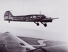
A series of dry cell batteries lining the aircraft floor powered the receiver, providing high voltage for the CRT through an ignition coil taken from a Ford car.
After hearing of the success, Watt called the team and asked if they would be available for testing in September, when a combined fleet of Royal Navy ships and RAF Coastal Command aircraft would be carrying out military exercises in the Channel.
[34] Following a suggestion from Watt to avoid Air Ministry channels, in October Bowen flew one of the Battles to the Metropolitan-Vickers (Metrovick) plant in Sheffield, where he pulled the DC generator off the engine,[e] dropped it on the table, and asked for an AC alternator of similar size and shape.
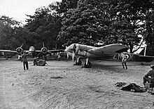
[58] New Blenheims eventually arrived at Martlesham, these having been experimentally converted to heavy fighters with the addition of four .303 British (7.7 mm) Browning machine guns and four 20mm Hispano autocannon, while removing the mid-upper turret to reduce weight by 800 lb (360 kg) and drag by a small amount.
The gear had to be re-fitted for the new aircraft, and the receivers and CRTs were mounted in the enlarged nose, allowing the operator to indicate corrections to the pilot through hand signals as a backup if the intercom failed.
Robert Hanbury Brown, a physicist who would later work on radar in the US, and Keith Wood joined them in August 1939, helping fitters keep the systems operational, and coming up with useful methods for interception.
[78] Bowen led a series of lectures at Bentley Priory, on the theory of radar guided night interception and concluded that the fighter would require a speed advantage of 20 to 25% over its target.
Apparently without informing Lardner of Bowen and Hanbury Brown's potential solution, or the fact that they could not work on it due to the ongoing installations, they agreed to have Lewis investigate the matter.
[93][m] At a further meeting on 23 May, Tizard, perhaps prompted by comments from Director of Signals (Air), suggested that the units were not suitable for operational use, especially due to low reliability, and should be confined to daylight training missions.
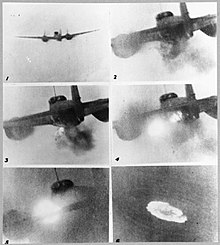
[99] The crews were bound to get lucky eventually, and this came to pass on the night of 22/23 July 1940, when a Blenheim IF of the FIU received direction from the Poling CH station and picked up the target at 8,000 feet (1.5 mi; 2.4 km) range.
[105] Dowding had been under almost continual criticism from all quarters long before this point; he was still in power after the normal retirement age for officers, had a prickly personality that earned him the nickname "Stuffy", and kept tight-fisted control over Fighter Command.
Dowding replied that the speed and altitude of modern aircraft made such efforts almost useless, stating that Phillips was proposing to "merely revert to a Micawber-like method of ordering them to fly about and wait for something to turn up".
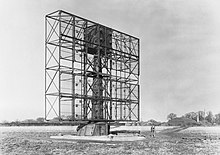
By this time the Army had made considerable progress on adapting the AI electronics to build a new radar for detecting ships in the English Channel, CD, with an antenna that was small enough to be swung in bearing.
Six copies of the prototype Ground Control Interception radars (GCI) were hand-built at AMES (Air Ministry Experimental Station) and RAE during November and December 1940, and the first went operational at RAF Sopley on New Year's Day 1941, with the rest following by the end of the month.
[115][q] Arthur Harris was appointed Air Officer Commanding-in-Chief of RAF Bomber Command on 22 February 1942, and immediately set about implementing his plan to destroy Germany through dehousing.
[117] On the night of 23 April 1942, a small raid was made against Exeter, followed the next day by a pronouncement by Gustaf Braun von Stumm that they would destroy every location found in the Baedeker tourist guides that was awarded three stars.
They introduced new sealing methods and an improved cathode, delivering two examples capable of generating 10 kW of power at 10 cm, an order of magnitude better than any existing microwave device.
Due to confused timing and better planning on the part of the AI team, they arrived at Worth Matravers from St Athan before the long convoy from Dundee could make its way south.
[125] Lovell adapted his parabolic antennas to the magnetron with relative ease, and the AIS team immediately detected a passing aircraft when they turned on the set for the first time on 12 August 1940.
In the late afternoon of 9 May 1943, a crew from IV/NJG.3 defected to the UK by flying their fully equipped Ju 88R-1 night fighter, D5+EV, to RAF Dyce in Scotland, giving the TRE their first direct look at the Lichtenstein.
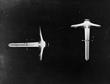
[137] In 1940, Hanbury Brown wrote a paper On Obtaining Visuals from AI Contacts which demonstrated mathematically that the time delays inherent to the interception system were seriously upsetting the approach.
[141] Continued work displayed a number of minor problems, and the decision was made to introduce a redesigned unit with significant improvements in packaging, insulation, and other practical changes.
[144] Starting in the summer of 1942 the TRE development team began experimenting with systems to project the display onto the windscreen, and by October had combined this with an image of the existing GGS Mk.
IV system worked on a single frequency, it naturally lent itself towards the Yagi antenna design, which had been brought to the UK when the Japanese patents were sold to the Marconi Company.
[165] The rapid introduction of new types of radars working on different frequencies meant the IFF system had to respond to an ever-increasing list of signals, and the direct response of the Mk.
Lorenz, or Standard Beam Approach as it was known in the UK, used a single transmitter located off the far end of the active runway that was alternately connected to one of two slightly directional antennas using a motorized switch.


