Axonometry
Axonometry is a graphical procedure belonging to descriptive geometry that generates a planar image of a three-dimensional object.
The result of an axonometric procedure is a uniformly-scaled parallel projection of the object.
In general, the resulting parallel projection is oblique (the rays are not perpendicular to the image plane); but in special cases the result is orthographic (the rays are perpendicular to the image plane), which in this context is called an orthogonal axonometry.
In technical drawing and in architecture, axonometric perspective is a form of two-dimensional representation of three-dimensional objects whose goal is to preserve the impression of volume or relief.
It can be considered a conical perspective conique whose center has been pushed out to infinity, i.e. very far from the object observed.
Pohlke's theorem is the basis for the following procedure to construct a scaled parallel projection of a three-dimensional object:[1][2] In order to obtain undistorted results, select the projections of the axes and foreshortenings carefully (see below).
In order to produce an orthographic projection, only the projections of the coordinate axes are freely selected; the foreshortenings are fixed (see de:orthogonale Axonometrie).
Only for suitable choices of angles and foreshortenings does one get undistorted images.
The next diagram shows the images of the unit cube for various angles and foreshortenings and gives some hints for how to make these personal choices.
The parameters in the diagram at right (e.g. of the house drawn on graph paper) are:
In this case [4][5] These angles are marked on many German set squares.
Advantages of an engineer projection: For more details: see de:Axonometrie.
[6][7] For example: Such axonometries are often used for city maps, in order to keep horizontal figures undistorted.
In the diagram, the circle contained in the front face is undistorted.
If the image of a circle is an ellipse, one can map four points on orthogonal diameters and the surrounding square of tangents and in the image parallelogram fill-in an ellipse by hand.
A better, but more time consuming method consists of drawing the images of two perpendicular diameters of the circle, which are conjugate diameters of the image ellipse, determining the axes of the ellipse with Rytz's construction and drawing the ellipse.
In a general axonometry of a sphere the image contour is an ellipse.
As the diagram shows, an ellipse as the contour of a sphere might be confusing, so, if a sphere is part of an object to be mapped, one should choose an orthogonal axonometry or an engineer projection or a standard isometry.


The left and the far right images look more like prolonged cuboids instead of a cube.


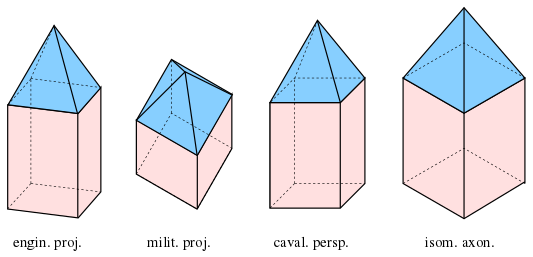
dimetric military projection: , dimetric engineering and cavalier projections: , isometric axonometry:


