Euler–Bernoulli beam theory
It covers the case corresponding to small deflections of a beam that is subjected to lateral loads only.
By ignoring the effects of shear deformation and rotatory inertia, it is thus a special case of Timoshenko–Ehrenfest beam theory.
It was first enunciated circa 1750,[2] but was not applied on a large scale until the development of the Eiffel Tower and the Ferris wheel in the late 19th century.
Following these successful demonstrations, it quickly became a cornerstone of engineering and an enabler of the Second Industrial Revolution.
Prevailing consensus is that Galileo Galilei made the first attempts at developing a theory of beams, but recent studies argue that Leonardo da Vinci was the first to make the crucial observations.
Da Vinci lacked Hooke's law and calculus to complete the theory, whereas Galileo was held back by an incorrect assumption he made.
plane, and the relevant second moment of area is where it is assumed that the centroid of the cross section occurs at
(known as the flexural rigidity) is a constant, so that This equation, describing the deflection of a uniform, static beam, is used widely in engineering practice.
The stresses in a beam can be calculated from the above expressions after the deflection due to a given load has been determined.
Because of the fundamental importance of the bending moment equation in engineering, we will provide a short derivation.
resulting from this stress, is given by This is the differential force vector exerted on the right hand side of the section shown in the figure.
The expression for the fibers in the upper half of the beam will be similar except that the moment arm vector will be in the positive
the bending moment vector exerted on the right cross section of the beam the expression where
is the mass per unit length, the second term represents the potential energy due to internal forces (when considered with a negative sign), and the third term represents the potential energy due to the external load
This equation can be solved using a Fourier decomposition of the displacement into the sum of harmonic vibrations of the form where
Thus the maximum principal stress in the beam may be neither at the surface nor at the center but in some general area.
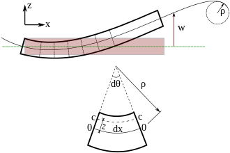
For small deflections, the element does not change its length after bending but deforms into an arc of a circle of radius
The slope of the beam is approximately equal to the angle made by the neutral surface with the
As an example consider a cantilever beam that is built-in at one end and free at the other as shown in the adjacent figure.
(the length of the beam), these statements translate to the following set of boundary conditions (assume
where M is the magnitude of a point torque, the boundary conditions appropriate for some common cases is given in the table below.
Boundary conditions are, however, often used to model loads depending on context; this practice being especially common in vibration analysis.
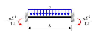
In that case the governing equation and boundary conditions are: Alternatively we can represent the point load as a distribution using the Dirac function.
These are equivalent boundary value problems, and both yield the solution The application of several point loads at different locations will lead to
Use of the Dirac function greatly simplifies such situations; otherwise the beam would have to be divided into sections, each with four boundary conditions solved separately.
Dynamic phenomena can also be modeled using the static beam equation by choosing appropriate forms of the load distribution.
The bending moment varies linearly from one end, where it is 0, and the center where its absolute value is PL / 4, is where the risk of rupture is the most important.
[5] Solutions for several other commonly encountered configurations are readily available in textbooks on mechanics of materials and engineering handbooks.
Therefore, additional techniques such as linear superposition are often used to solve statically indeterminate beam problems.
The resulting strains take the form: From the principle of virtual work, the balance of forces and moments in the beams gives us the equilibrium equations where