Carnot cycle
By Carnot's theorem, it provides an upper limit on the efficiency of any classical thermodynamic engine during the conversion of heat into work, or conversely, the efficiency of a refrigeration system in creating a temperature difference through the application of work to the system.
In a Carnot cycle, a system or engine transfers energy in the form of heat between two thermal reservoirs at temperatures
(referred to as the hot and cold reservoirs, respectively), and a part of this transferred energy is converted to the work done by the system.
The cycle is reversible, and entropy is conserved, merely transferred between the thermal reservoirs and the system without gain or loss.
When heat moves from the hot to the cold reservoir, the system applies work to the environment.
The gas is allowed to expand, doing work on the surroundings by pushing up the piston (Stage One figure, right).
Heat QH > 0 is absorbed from the hot temperature reservoir, resulting in an increase in the entropy
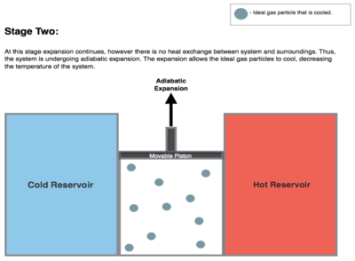
The entropy remains unchanged as no heat Q transfers (Q = 0) between the system (the gas) and its surroundings.
An amount of energy earned by the gas from this work exactly transfers as a heat energy QC < 0 (negative as leaving from the system, according to the universal convention in thermodynamics) to the cold reservoir so the entropy of the system decreases by the amount
During this step, the surroundings do work on the gas, pushing the piston down further (Stage Four figure, right), increasing its internal energy, compressing it, and causing its temperature to rise back to the temperature infinitesimally less than TH due solely to the work added to the system, but the entropy remains unchanged.
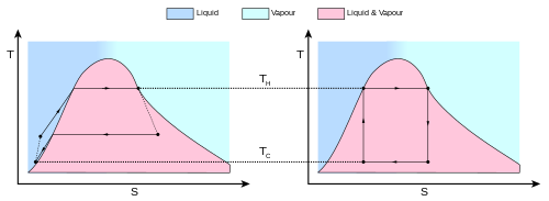
The behavior of a Carnot engine or refrigerator is best understood by using a temperature–entropy diagram (T–S diagram), in which the thermodynamic state is specified by a point on a graph with entropy (S) as the horizontal axis and temperature (T) as the vertical axis (Figure 2).
The area inside the cycle is then the difference between the two (the absorbed net heat energy), but since the internal energy of the system must have returned to its initial value, this difference must be the amount of work done by the system per cycle.
Referring to Figure 1, mathematically, for a reversible process, we may write the amount of work done over a cyclic process as: Since dU is an exact differential, its integral over any closed loop is zero and it follows that the area inside the loop on a T–S diagram is (a) equal to the total work performed by the system on the surroundings if the loop is traversed in a clockwise direction, and (b) is equal to the total work done on the system by the surroundings as the loop is traversed in a counterclockwise direction.
The total amount of heat transferred from the hot reservoir to the system (in the isothermal expansion) will be
and the total amount of heat transferred from the system to the cold reservoir (in the isothermal compression) will be
That is, all the processes that compose it can be reversed, in which case it becomes the Carnot heat pump and refrigeration cycle.
This time, the cycle remains exactly the same except that the directions of any heat and work interactions are reversed.
A corollary to Carnot's theorem states that: All reversible engines operating between the same heat reservoirs are equally efficient.
Rearranging the right side of the equation gives what may be a more easily understood form of the equation, namely that the theoretical maximum efficiency of a heat engine equals the difference in temperature between the hot and cold reservoir divided by the absolute temperature of the hot reservoir.
Looking at this formula an interesting fact becomes apparent: Lowering the temperature of the cold reservoir will have more effect on the ceiling efficiency of a heat engine than raising the temperature of the hot reservoir by the same amount.
In the real world, this may be difficult to achieve since the cold reservoir is often an existing ambient temperature.
An entropy change per cycle is made, for example, if there is friction leading to dissipation of work into heat.
In mesoscopic heat engines, work per cycle of operation in general fluctuates due to thermal noise.
In addition, real engines that operate along the Carnot cycle style (isothermal expansion / isentropic expansion / isothermal compression / isentropic compression) are rare.
Nevertheless, Equation 3 is extremely useful for determining the maximum efficiency that could ever be expected for a given set of thermal reservoirs.
For the Carnot cycle, or its equivalent, the average value ⟨TH⟩ will equal the highest temperature available, namely TH, and ⟨TC⟩ the lowest, namely TC.
The first prototype of the diesel engine was based on the principles of the Carnot cycle.
The Carnot heat engine is, ultimately, a theoretical construct based on an idealized thermodynamic system.
On a practical human-scale level the Carnot cycle has proven a valuable model, as in advancing the development of the diesel engine.
However, on a macroscopic scale limitations placed by the model's assumptions prove it impractical, and, ultimately, incapable of doing any work.


Q C (energy lost to the cold reservoir) can be seen as a direct subtraction, or expressed as the sum of a negative quantity, which can lead to different conventions.