Cyclonic separation
A high-speed rotating (air)flow is established within a cylindrical or conical container called a cyclone.
Particles larger than the cut point will be removed with a greater efficiency, and smaller particles with a lower efficiency as they separate with more difficulty or can be subject to re-entrainment when the air vortex reverses direction to move in direction of the outlet.
The primary air flow containing the particulates enters from the bottom of the cyclone and is forced into spiral rotation by stationary spinner vanes.
The secondary air flow also allows the collector to optionally be mounted horizontally, because it pushes the particulate toward the collection area, and does not rely solely on gravity to perform this function.
Large scale cyclones are used in sawmills to remove sawdust from extracted air.
Cyclones are also used in industrial and professional kitchen ventilation for separating the grease from the exhaust air in extraction hoods.
Some are small enough to be worn clipped to clothing, and are used to separate respirable particles for later analysis.
[3] Analogous devices for separating particles or solids from liquids are called hydrocyclones or hydroclones.
These may be used to separate solid waste from water in wastewater and sewage treatment.
The main vortex spirals downward and carries most of the coarser dust particles.
The inner vortex, created near the bottom of the cyclone, spirals upward and carries finer dust particles.
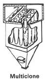
Multiple-cyclone separators consist of a number of small-diameter cyclones, operating in parallel and having a common gas inlet and outlet, as shown in the figure, and operate on the same principle as single cyclone separators—creating an outer downward vortex and an ascending inner vortex.
A single-chamber cyclone separator of the same volume is more economical, but doesn't remove as much dust.
The secondary air flow increases the speed of the cyclonic action making the separator more efficient; it intercepts the particulate before it reaches the interior walls of the unit; and it forces the separated particulate toward the collection area.
If one considers an isolated particle circling in the upper cylindrical component of the cyclone at a rotational radius of
from the cyclone's central axis, the particle is therefore subjected to drag, centrifugal, and buoyant forces.
Determining the outward radial motion of each particle is found by setting Newton's second law of motion equal to the sum of these forces: To simplify this, we can assume the particle under consideration has reached "terminal velocity", i.e., that its acceleration
In most cases, this solution is used as guidance in designing a separator, while actual performance is evaluated and modified empirically.
For example, the geometry of the separator is not considered, the particles are assumed to achieve a steady state and the effect of the vortex inversion at the base of the cyclone is also ignored, all behaviours which are unlikely to be achieved in a cyclone at real operating conditions.
More complete models exist, as many authors have studied the behaviour of cyclone separators.
[5] Simplified models allowing a quick calculation of the cyclone, with some limitations, have been developed for common applications in process industries.
[6] Numerical modelling using computational fluid dynamics has also been used extensively in the study of cyclonic behaviour.
[7][8][9] A major limitation of any fluid mechanics model for cyclone separators is the inability to predict the agglomeration of fine particles with larger particles, which has a great impact on cyclone collection efficiency.