Multiplexer
In electronics, a multiplexer (or mux; spelled sometimes as multiplexor), also known as a data selector, is a device that selects between several analog or digital input signals and forwards the selected input to a single output line.
[2] A multiplexer makes it possible for several input signals to share one device or resource, for example, one analog-to-digital converter or one communications transmission medium, instead of having one device per input signal.
Multiplexers can also be used to implement Boolean functions of multiple variables.
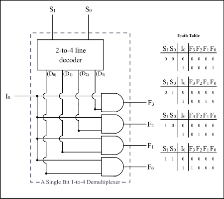
Conversely, a demultiplexer (or demux) is a device that takes a single input signal and selectively forwards it to one of several output lines.
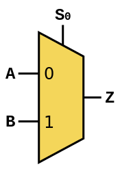
[3] The schematic symbol for a multiplexer is an isosceles trapezoid with the longer parallel side containing the input pins and the short parallel side containing the output pin.
[4] The schematic on the right shows a 2-to-1 multiplexer on the left and an equivalent switch on the right.
Multiplexers are part of computer systems to select data from a specific source, be it a memory chip or a hardware peripheral.
A computer uses multiplexers to control the data and address buses, allowing the processor to select data from multiple data sources In digital communications, multiplexers allow several connections over a single channel, by connecting the multiplexer's single output to the demultiplexer's single input (Time-Division Multiplexing).
At the receiving end of the data link a complementary demultiplexer is usually required to break the single data stream back down into the original streams.
This would be the case when, for instance, a multiplexer serves a number of IP network users; and then feeds directly into a router, which immediately reads the content of the entire link into its routing processor; and then does the demultiplexing in memory from where it will be converted directly into IP sections.
Both circuit elements are needed at both ends of a transmission link because most communications systems transmit in both directions.
In analog circuit design, a multiplexer is a special type of analog switch that connects one signal selected from several inputs to a single output.
In larger multiplexers, the number of selector pins is equal to
is the output: Which can be expressed as a truth table: Or, in simpler notation:
While this is mathematically correct, a direct physical implementation would be prone to race conditions that require additional gates to suppress.
Since digital logic uses binary values, powers of 2 are used (4, 8, 16) to maximally control a number of inputs for the given number of selector inputs.
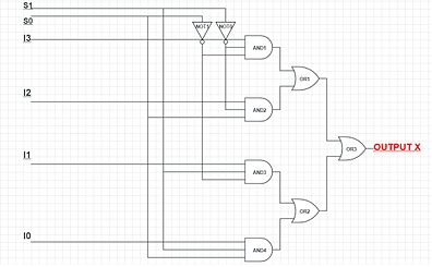
The Boolean equation for a 4-to-1 multiplexer is: Which can be expressed as a truth table: The following 4-to-1 multiplexer is constructed from 3-state buffers and AND gates (the AND gates are acting as the decoder):
The two 4-to-1 multiplexer outputs are fed into the 2-to-1 with the selector pins on the 4-to-1's put in parallel giving a total number of selector inputs to 3, which is equivalent to an 8-to-1.
For 7400 series part numbers in the following table, "x" is the logic family.
This means that any function of the selection bits can be constructed by logically OR-ing the correct set of outputs.
For 7400 series part numbers in the following table, "x" is the logic family.
Bi-directional multiplexers are built using analog switches or transmission gates controlled by the select pins.
[6] Multiplexers can also be used as programmable logic devices, to implement Boolean functions.
Any Boolean function of n variables and one result can be implemented with a multiplexer with n selector inputs.
[7] Multiplexers have found application in unconventional stochastic computing (SC), particularly in facilitating arithmetic addition.
In this paradigm, data is represented as a probability bitstream where the number of '1' bits signifies the magnitude of a value.
Moreover, more sophisticated applications of multiplexers include serving as Bernstein polynomial function generator,[8] capable of producing arbitrary mathematical functions within the SC domain.
Recent research has also revealed that combinations of multiplexers can facilitate large-scale multiply-accumulate operation,[9] demonstrating feasibility in accelerating convolutional neural network on field-programmable gate arrays.