Distributed-element circuit
Conventional circuits consist of individual components manufactured separately then connected together with a conducting medium.
After the war their use was limited to military, space, and broadcasting infrastructure, but improvements in materials science in the field soon led to broader applications.
The lumped model completely fails at one-quarter wavelength (a 90° phase change), with not only the value, but the nature of the component not being as predicted.
Although the changeover is usually somewhere in the 100-to-500 MHz range, the technological scale is also significant; miniaturised circuits can use the lumped model at a higher frequency.
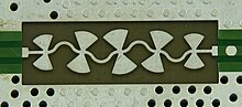
[2] The overwhelming majority of distributed-element circuits are composed of lengths of transmission line, a particularly simple form to model.
Although an arbitrary shape can be analysed with Maxwell's equations to determine its behaviour, finding useful structures is a matter of trial and error or guesswork.
There is no equivalent in lumped circuits for a fixed delay, although an approximation could be constructed for a limited frequency range.
However, parasitic elements and resistive losses in lumped components are greater with increasing frequency as a proportion of the nominal value of the lumped-element impedance.
Distributed-element designs tend to have greater power-handling capability; with a lumped component, all the energy passed by a circuit is concentrated in a small volume.
Open wire is a pair of parallel uninsulated conductors used, for instance, for telephone lines on telegraph poles.
Although coaxial distributed-element devices were commonly manufactured during the second half of the 20th century, they have been replaced in many applications by planar forms due to cost and size considerations.
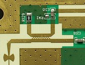
[8] The majority of modern distributed-element circuits use planar transmission lines, especially those in mass-produced consumer items.
Waveguides have the advantages of lower loss and higher quality resonators over conducting lines, but their relative expense and bulk means that microstrip is often preferred.
Waveguide mostly finds uses in high-end products, such as high-power military radars and the upper microwave bands (where planar formats are too lossy).
[16] A single, cascaded line one-quarter wavelength long forms a quarter-wave impedance transformer.
Cavity resonators can be used in many media, but are most naturally formed in waveguide from the already existing metal walls of the guide.
Although they are superficially similar to lumped inductors, helical resonators are distributed-element components and are used in the VHF and lower UHF bands.
The profile that achieves a specified match in the shortest length is known as a Klopfenstein taper and is based on the Chebychev filter design.
[41] A power divider is often constructed as a directional coupler, with the isolated port permanently terminated in a matched load (making it effectively a three-port device).
Transmission of early transatlantic telegraph had been difficult and slow due to dispersion, an effect which was not well understood at the time.
[56] Warren P. Mason was the first to investigate the possibility of distributed-element circuits, and filed a patent[57] in 1927 for a coaxial filter designed by this method.
The acoustic work had come first, and Mason's colleagues in the Bell Labs radio department asked him to assist with coaxial and waveguide filters.
[59] Before World War II, there was little demand for distributed-element circuits; the frequencies used for radio transmissions were lower than the point at which distributed elements became advantageous.
These frequencies require long antennae for efficient operation, and this led to work on higher-frequency systems.
A key breakthrough was the 1940 introduction of the cavity magnetron which operated in the microwave band and resulted in radar equipment small enough to install in aircraft.
[61] The wartime work was mostly unpublished until after the war for security reasons, which made it difficult to ascertain who was responsible for each development.
An important centre for this research was the MIT Radiation Laboratory (Rad Lab), but work was also done elsewhere in the US and Britain.
Microstrip, invented in 1952,[72] became a commercial rival of stripline; however, planar formats did not start to become widely used in microwave applications until better dielectric materials became available for the substrates in the 1960s.
Its advantages (compact size and high quality) were first pointed out[74] by R. D. Richtmeyer in 1939, but materials with good temperature stability were not developed until the 1970s.
Cohen was the first to explicitly identify the class of fractal antennae after being inspired by a lecture of Benoit Mandelbrot in 1987, but he could not get a paper published until 1995.