Eye pattern
It is a tool for the evaluation of the combined effects of channel noise, dispersion and intersymbol interference on the performance of a baseband pulse-transmission system.
From a mathematical perspective, an eye pattern is a visualization of the probability density function (PDF) of the signal, modulo the unit interval (UI).
Typically a color ramp is applied to the PDF in order to make small brightness differences easier to visualize.
If the signals are too long, too short, poorly synchronized with the system clock, too high, too low, too noisy, or too slow to change, or have too much undershoot or overshoot, this can be observed from the eye diagram.
This may be done by measuring an actual electrical system with an oscilloscope of sufficient bandwidth, or by creating synthetic data with a circuit simulator in order to evaluate the signal integrity of a proposed design.
Interpolation may also be applied at this time in order to increase the number of samples per unit interval (UI) and produce a smooth, gap-free plot which is more visually appealing and easier to understand.
This approach can work adequately for stable signals in which the symbol rate remains exactly the same over time, however inaccuracies in the system mean that some drift is inevitable so it is rarely used in practice.
Most high speed serial signals, such as PCIe, DisplayPort, and most variants of Ethernet, use a line code which is intended to allow easy clock recovery by means of a PLL.
Since this is how the actual receiver works, the most accurate way to slice data for the eye pattern is to implement a PLL with the same characteristics in software.
Correct PLL configuration allows for the eye to conceal the effects of spread spectrum clocking and other long-term variation in the symbol rate which do not contribute to errors at the receiver, while still displaying higher frequency jitter.
Large amounts of data may be needed to provide an accurate representation of the signal; tens to hundreds of millions of UIs are frequently used for a single eye pattern.
If the data rate is high enough or the channel is lossy enough, the signal may not even reach its full value during a fast 0-1-0 or 1-0-1 transition, and only stabilize after a run of several identical bits.
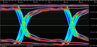
The image below shows a 1.25 Gbit/s NRZ signal after passing through a lossy channel - an RG-188 coaxial cable approximately 12 feet (3.65 meters) in length.